铁头九头蛇车拍安装教程
i'm a savage i'm a strap drop the classic drop the classic drop the class drop the class super stylish super stylish at the magic at the magic sort of matter gotta match gotta match who was that up the weapon nice to mind never try never try alright guys welcome back to another episode with full lair media today we got something really exciting if you want to go check out the unboxing video of the alien car mount by tilta i got an unboxing video i went over everything that comes in the box but today we got something really exciting if you can hear that we're gonna test out the mount i put some custom mounts on this car will go over those so let's go check that out right now so i'm gonna go but i do like the fact that it's nice and sturdy obviously i can come up even higher and i do have the extra suction cup so i can do this the normal way once, i get the car wrapped yeah i'm gonna get the whole car wrapped because if i want to get up really high i can actually just use the suction cups it can mount up here like you go one two three and then the whole contraption and you can mount this way up here if i wanted to get a really high shot of a car or whatever i want so right now i can go all the way to here to be honest for cars 90 percent of the time you want nice low shop right you always want the speed of the road if you're up too high it doesn't look like you're going as fast whereas if you're nice and low you're gonna get the road going by really fast and you're gonna get that that really good feeling of speed is upset now dude like holy super smooth like there was a lot of complaints with this about how like rough fit was when you're driving with not enough weight or a red camera like man that was smooth i don't even think the gimbal is on super smooth mode either i really love this thing i'm actually really impressed i actually was i was thinking the footage is gonna be all crappy and shaky so yeah i'm really impressed i'm really happy it is it make people all love my car all over again right so the same with the shadows and stuff yeah actually we do like get full quality it's pretty good off yeah so basically the way that i've set this up here is not one of the ways that tilter has designed or in the manual this is not in the manual the way that i've set it up here but i did get it to work and i like the fact that i can have this extended i can actually pull this back up and then i can have it up higher or lower and i can move this around so that it's up and down so ready to go jimmy let's do this oh that white picket fan is so sexy 走 me and now hop back in front sea and then we'll try to do the whole loop again but i'll try to get fire the backend yeah so we'll do one for the front and yeah okay sweet pump stokes really good okay guys i really hope you enjoyed this episode we really had a lot of fun with this and i think i'm really happy in conclusion i'm happy with this setup and i've already worked to advance it with some monitors and some other things so all that and more coming up on another episode thanks so much please hit subscribe follow along leave any comments below if you have any questions see you in the next one。

粉丝11.9万获赞158.0万
相关视频
 13:04查看AI文稿AI文稿
hi, everyone today, i will show you how to assemble the tilta hydra alien car mount system begin by separating l four and the cross connector next take a small suction cup and insert it at the end of l four lock down the suction cup with a red washer do the same thing at the other end of l four with the other small suction cup remove the protection caps from the suction cups position the suction cups accordingly activate the suction cups by depressing the suction valve until the line is no longer visible slide the cross connector to the center of l four remove and expand the dev tel plates l one, l two and l three from the case mount the apparatus as shown and lock down with a red washer you may want to use a small piece of foam to prevent the apparatus from scratching the car install the large suction cup at the bottom and secure with a red washer activate the suction cup by the pressing the suction valve until the line is no longer visible adjust the support arm as necessary remove the spring arm with hydraulic piston from the case install the spring arm upright and lock down with the red washer next grab the shock absorbing head connector with power supply modules install the head to the arm and lock down via the red washer remove the quick release plate from the head screw the quick release plate onto the runn as two power supply base plate attach the quick release plate with power supply base plate to the shock absorbing head attach the rv balance run and s to gimbal secure the power supply base plate with the gimbal via the hex screw and arm attach batteries plug in the two pin to p tap cable increase the tension of the spring arm by adjusting the knob the arm should fall even and horizontally tighten all red washers with the tool increase the dampening of the piston for bumpy terrain attach the remote control receiver module for rs, two turn on the gimbal auto calibrate now you can remotely control the roton s two gimbal head you can configure the hydra alien in multiple positions now we will show you how to mount to the side door of a car mount the suction cups on either end of l three with the cross connector at the center attach l one to the cross connector and lock down via the red washer attach the large suction cup to the bottom and secure via the red washer install the spring arm install the shark absorbing head connector with power supply module slide in the power supply base plate attach the rv balance gimbal and secure the power supply base plate with the gimbal via the hex screw and arm attach batteries plug in the two pin to p tab cable attach the remote control receiver module for rs, two tighten all the red washers with the tool increase the tension of the spring arm by adjusting, the knob the arm should fall even and horizontally turn on the gimbal and you're ready to shoot now we will show you how to mount the hydra alien to the side door of the car with the gimbal facing the driver mount the small suction copes on either end of l three with the cross connector at the center attach l one to the cross connector and lock down via the red washer attach the large suction cup to the bottom and secure via the red washer slide the dovetail support plate l four to the top of l one slide l two to the bottom of the apparatus then slide l two on to l four to create a level shelf adjust l two accordingly attach the steel wire shock absorbing head with power supply module to l for and secure via red washer slide in the power supply base plate attach the already balanced gimbal and secure the power supply base plate with the gimbal via the hex grew and arm attach batteries plug in the two pin to p tab cable attach the remote control receiver module for rs, two turn on the gimbal face toward the driver and you're ready to shoot now we will show you how to mount the hydro alien to the rear corner of a car start by attaching the small suction cups to each end of l four with the cross connector in the center attach the apparatus with suction cup attached at the top secure via red washer install the spring arm upright and lock down via redwasher install the shock absorbing head connector with power supply module slide in the power supply base plate attach the already balanced gimbal and secure the power supply base plate with the gimbal via hex crew and arm attach batteries plug in two pin to p tab cable attach the remote control receiver module for rs, two plug in the limo cable to the remote control receiver modules cleanly mount the cables onto the cable ties use the mini suction cup cable ties to feed cable to the passenger side window plug in the limo cable into the controller to control the gimbal now we will configure the hydra alien on the hood of the car add the suction cups and dovetail support to create a t shaped apparatus suction cup the apparatus to the hood of the car attach the steel wire shock absorbing head with power supply modules and secure via the red washer to l three slide the full balanced gimbal with power supply module remote control receiver module and quick release already installed add batteries plug in the two pin to p tap cable tighten all red washers with the tool turn on the gimbal and you're ready to shoot now we will configure the hydrail in onto the back of a car attach the mini suction cups to both ends of l four with the cross connector at the center activate the suction cups by depressing the suction valve until the line is no longer visible slide the cross connector to the center of l four install the suction cup at the top of the apparatus connect the middle plate to the cross connector activate the suction cups by depressing the suction valve until the line is no longer visible secure via the red washer adjust the plates so that the outermost plate is perpendicular to the ground install the spring arm upright lock down with the red washer install the shock absorbing head connector with our supply module secure via the red washer slide in the power supply of base plate attach the already balanced kimble attach batteries secure the power supply base plate with the gimbal via the hex crew and arm increase the tension of the spring arm by adjusting the knob the arm should fall even and horizontally tighten all red washers with the tool turn on the gimbal auto calibrate and you're ready to shoot。
100武汉影视器材 23:37查看AI文稿AI文稿
hi, this is nick from tilta and today we're going to take a look at how to set up and operate the hydra arm mini, the hydra arm mini is a portable lightweight and relatively easy to use system for filming moving vehicles from various angles at an affordable price the system packs up into three boxes, which are lightweight and easy to transport it features a modular design that allows the setup process to be as efficient as possible if you are shipping the hydra arm mini by air, you may need to rearrange some items into different cases in order to comply with your airlines oversized luggage requirements box one includes four suction cup mounts with support brackets as well as two fifty millimeter support pipes the pan axis module interior mounting hardware set, which includes one large monitor support bracket for the front passenger seats and is composed of two section cups, two articulating arms and one mounting bracket with multiple monitor mounting adapters the support set also includes two monitor support brackets for the rear passenger seats bucks, two includes tilt axis module and two sets of cable support rods box three includes two full sized crane arm pieces, a two pin limo to ptep power cable one crane arm end piece with a battery plate, a shock absorbing arm with a mounting plate two support cables, a remote control with communication cable, a power cable, a tool kit, two ratchet straps and various mounting hardware, we will now show you how to set up and install the hydraar mini in this following quick start guide this system is compatible with the majority of vehicles, but it is not fully compatible with all vehicles as the manufacturing of many vehicles differ it cannot be guaranteed that the roof and frame will not be damaged permanently marked or dented such risks are possible it is recommended to use the system with vehicles that have heavy duty frames with roofs that support a higher weight capacity that of which you'd find on most suvs additionally if your shoot has special requirements it is advised to choose a specific vehicle and weld a fixed bracket onto the roof or choose a vehicle with the infrastructure to create a mounting bracket that is permanently fixed to the roof as a designated camera crane vehicle to start make sure your vehicle's roof is free of any dust stir dirt and wipe it down with a cleaning solution if needed when installing the first suction cup please make sure that it is as close to the edge of the roof as possible while not interfering with the frame of the car as you will need to run an additional ratchet strap at a later step align your first suction cup once positioned add pressure and press down on the suction cup plunger when installing the second suction cup that you'll need to make sure there's approximately sixty nine centimeters of distance between the center of each of the rod mounts when working on the other side you can loosely line up the suction cups by eye and then make further adjustments as needed to install your first piece of support pipe please screw in the extension piece as most vehicles will require this you can then place the support pipe across so that it is inlined and being supported by both suction cup brackets and do the same for the other set before clamping down you'll want to make sure that the support pipes are relatively even and centered and then you can tighten them down finger tight is good for this point next you'll need to install the ratchet straps for additional support run one end of the strap around the support beam and down back into the vehicle pull the entirely through and move to the other side of the vehicle in a similar fashion run the strap around the support beam and then back into the vehicle next you'll want to run the strap through the ratchet making sure to get rid of as much slack as possible before ratching down you'll want this connection to be tight, but not too tight as to damage the vehicle you can then double check both sides to make sure everything is secure and repeat the same process for the back suction cups next, we're ready to install the pan exis module before installing make sure that the power port and information port on the back of the module are facing the back of the vehicle you'll need at least two people to lift this module and make sure the clamps are unlocked before lifting it onto the vehicle once in place you can tighten down the clamps, but make sure they are not too tight so that the module can still slide as this is not its final position next remove the locking washers on top of the four bolts on the pan axis module then you are ready to install the tilt access module although possible to install while closed it's recommended to open the top cover to get a better grip on the module again you will need at least two people to lift this module you will then need to align the four bolts on the pan access module with the fourth threads on the tilt access module you can then push both the pan and the tilt excess module towards the center of the vehicle and secure the final position by tightening down on the clamps next you only to further secure the tilt excess module to the pan x module by reinstalling the same locking washers over the bolts on the pan excess module repeat this process for all four bolts remember before operating all washers and clamps must be tightened down with an allen key it is recommended to double check these clamps throughout your shooting day you can then close the top cover first we will connect our controller communication cable to the back of the pan axis module then we will connect the cable to the back of the controller after that we will connect our power cable to the back of the pan access module you can then connect your power cable to your two hundred twenty volt power source in this case we're using a power converter with our thousand watt hour ecoflow battery but if you already have a two hundred twenty volt source you can connect to it directly when powering up your controller for the first time you will need to turn your center dial to its middle position you will then need to input your authorization key to obtain an activation key go to tilta com activate and introduce the product id on the remote control screen after reading the disclaimer in warnings it agree next we need to prepare our joysticks we'll double press the lock to unlock the screen and enter the main menu in the top right corner before selecting device info from there we can press joystick cowl this will recalibrate the joysticks and fix any issues that may have been caused during shipping we can then return to the main menu and lock the screen and you can turn on the motor by twisting the red stop button you can then turn the center dive one more to the right to activate control you can then use the joysticks to pan the motor to the side of the vehicle in order to have a better position in which to install the arm turn the system off by first turning the dial to the middle position next you can press the red stop button then you can rotate the center dial to the left in order to turn the entire system off you will then need to unplug first the power cable and then the controller communication cable and then power off your battery converter and unplug the system you are now ready to install the arm to start you will install the first part of the arm to the body of the tilt access module you will need to line up the pins on the back of the arm with the slots and then pull down to line them into place you can then use the included bolts and tools to secure six bolts to each section of the arm you will then be able to attach additional parts of the arm in a similar fashion once properly aligned the arm should be able to hold itself in place once the arm is assembled you can then install the two sets of cable support rods to start you'll need to mount the rod element of the cable support rod into the base of the tilt access module you can then use this additional support bracket and locking pin to further secure the support rod in place please note, if you're having issues aligning the bracket you can rotate it to extend it you can then connect the four additional support rods into the arm next you'll attach the support cables to the cable support rods to do this insert one end of the support cable into the support rod and lock it in place with a pin you can then run the cable through the integrated slots on the other two support rods and lock the end in with a pin you can then adjust the tension by tightening the tension adjust and screw on the support cables keep in mind you'll want this to be fairly taught but not too tight next you can install the shock absorbing arm this connects in a similar fashion with two pins that can be slid into place and then further secured with four bolts you are now ready to attach your gimbal for this setup we're using an rs three pro with our power supply base plate for dgi ronin connected with the quick release plate that is included with the shock absorbing arm you can then connect the gimbal via the quick release plate receiver and lock it into place position the gimbal so that the screen is facing outward for easy access next you can undo your locks to make sure your camera system is balanced and make any adjustments as needed you can then attach a v mount or gold mom battery for power and connect the included detep to two pin power cable you can also run the cable through the shock absorbing arm in order to keep it more tidy once the power cable is connected you can then turn on the gimbal and make any calibrations or adjustments as necessary you can then reconnect power to the arm by first connecting the controller communication cable to the base of the pan access module and then reconnecting the controller and then you can reconnect the power cable to the base of the pan access module and then reconnect the power cable to your converter before powering on the battery and then powering on the converter and power on the controller by turning the center dial to the middle position after reading the disclaimer, you can then press accept to boot up the system once powered on you'll notice a green led indicator on the side of the pan axis module this green solid led indicates that the arm is powered and control is active if the light is flickering that implies there's a communication issue, please check the status of the led on the side of your pan x's module before moving forward if you need to move the arm manually you can press the button next to the green led indicator to disable the controller this button will start flashing indicating that you can now manually move the arm by hand when the arm is not installed you can also use this button in order to raise the arm to its highest position in order to change out an internal component we're now going to look at how to balance the shock absorbing arm the goal is to adjust the dampening so that when you release the gimbal it quickly returns to center you can adjust the vertical or tilt dampening in a similar fashion by adjusting the small dial on top of the arm, please note this comes preset for a five kilogram payload meaning in most cases this will not need to be adjusted for better control of your gimbal while on a moving vehicle we recommend using the dgi external gps module next, we'll take a look at how to to calibrate the horizon of the arm to power it on turn the dial in the center to the middle position after reading the disclaimer press agree you'll then need to wait approximately thirty seconds for the system to fully boot up the first thing to look at would be the connection status between the arm and controller you can see that the arm is connected to the controller here you can now see the motor status here to engage the motor turn the red stop button to the right you'll notice the red motor indicator changes to blue you can now activate the controller by turning the center dial to the right the red controller indicator has now turned blue you will then need to position the arm until it appears level in relation to your vehicle note this may not align with zero on the screen ui to open the main menu first unlock the screen by double tapping the lock icon you can open the main menu here to calibrate this new horizon position press device info then press gyro you will then hear a beep to save the setting you will need to restart the system by turning off control and then pressing the red button to disengage the motor before turning the dial all the way to the left to power off the system we'll now take a look at how to adjust the joystick settings on the controller first test both of your joysticks by applying slight pressure on each of them to see which is a line to which function then unlock the screen by double tapping the lock icon and open the main menu in the top right corner then press settings to open up joystick settings here you can see which joystick is assigned to which axis to change the configuration press the set button on either of the joysticks you can also change the directions of both the pan and tilt axis to be counterclockwise or clockwise here is where we can enable gimbal control here is where you can electronically adjust the motors for different payloads and here is an option for enabling additional stabilization you can then test the configuration of the joysticks without exiting the menu and you can press return to return to the home screen now we're going to take a look at how to set your pan axis position as well as how to set a and b limits for both tilt and pan motors to start you will need to adjust the position of your arm so that it is directly in front of your vehicle don't worry about the number readout on the ui as this is what we are calibrating to become the new zero unlock the screen by double tapping the unlock key once your arm is physically in position press the red button in the center to reset your zero point the physical position of your arms should now align with the ui of your controller in order to set a limitation for the pan axis first find your left most point you can set this as your a point by pressing the pan limit settings button then adjust your arm to its right most point and then lock in your b point by again pressing the button the arm will now be unable to travel past these set points you can remove these points at any time by pressing the pan limit settings button for a third time to set your limits for the tilt axis at first find your maximum height set your a point by pressing the tilt limit settings button then move the arm to its lowest safe position and lock in your b point with the same button the arm will now be unable to exceed the range that you set for the tilt motor you can remove these limits at any time by pressing the tilt limit settings button for a third time please note we only recommend operating the arm when you have tilt limits activated now going to take a look at how to adjust the speed and dampening you can find the dials to control speed and dampening for the pan axis as well as their indicators on the ui on the left hand side of the screen to adjust the speed simply adjust the dials you will then find the dampening and speed dials for the tilt axis on the right hand side as well as the corresponding indicators on the ui, the lower, the speed, the slower, the arm will physically travel the higher, the speed, the faster, the arm will physically travel and the more sensitive the joysticks will be the lower the dampening the more gradually the arm will come to a stop the higher the dampening the faster it will stop next we're going to take a look at how to control an rs, two or rs, three pro through the controller first unlock the screen select gimbal in the main menu the first thing you'll notice is that you're able to manually adjust the channel number if needed the next option, you'll notice will allow you to calibrate the wheels above the joysticks located on the top of the controller to calibrate simply hold one wheel to the left side and release then to the right and release the indicators should change from red to blue you can then press the button in the center to return to the gimbalman to connect your gimbal to the controller press the easy mode button after installing the tilto wireless receiver double tap the power button and you will see a blinking red light back on the controller a number one should appear and pressing connect should link the two the wireless receiver modules light should turn solid green indicating you have a connection you can then exit the menu by pressing return you can then return to the joystick menu by accessing the main menu and pressing settings you can then press the button in the center to enable promode you'll notice one joystick now has full control of the arm while the other has full control of your gimbal you can swap which joystick controls what by pressing set? you can also adjust the direction of the gimbal and arm to be counterclockwise or clockwise for any of the axes you can then use the right finger wheel over the joystick to control dial functions such as roll and you can use the finger wheel over the arm joystick to control the speed of your gimbal please note the controller will beep to indicate you are increasing or decreasing the speed you also find a record button which can be used when you using optional run stop cables for the rs, two or rs, three pro situation you may find yourself in is where the ui the controller does not line up with the direction the arm is moving as you can see removing the joystick to the left and the ui is moving to the right and vice versa in order to correct this we're going to unlock the screen and go into the device info setting on the menu here we'll find pan ui cow which we can activate by holding down the record button and then pressing you can then return to the main menu and find that the direction of the arm joystick and ui is all aligned you'll follow similar steps to fix this issue with the tilt axis as you can see the arm is physically traveling up but the indicator is moving down in vice versa we'll go back to device info on the main menu hold down the record button and press the tilt ui cow button and we'll return to the main menu to find the direction of the tilt axis is now realigned with the ui we're now going to look at a few remaining options in the menu of the controller we're going to open up the main menu and select device info on the top right you'll see an option to change the language between english and chinese below that is an option for firmer upgrades we'll have more information on how to do that on our website next to that is a service button that is only used by our service engineers when completing repairs above that you'll find the gyro cow button which recalibrates the first horizon of the arm above that you'll find joystick cow which is going to allow you to reset the center point of the joysticks should you encounter any joystick drifting or issues with controls in the bottom left corner you'll see an option to factory reset the controller, please note, this will require your authorization key so make sure you have that handy before resetting the controller above that you'll see the system's current firmware as well as the device info which is what the controller will read as when connected to a computer next we'll take a look at how to install the interior monitor mounting hardware that's included with the hydra armony to start we're going to install the front seat monitor mounting bracket which is composed of two suction cups and two large noga arms as well as one large monitor bracket you can then loosely configure the bracket in a position that you feel will best suit your vehicle once you found a good position you can attach the suction cups to the windshield and adjust the articulating arms in order to better position the monitor bracket you can then attach up to three monitors via quarter twenty threads and adjust the position of these monitor brackets via the quarter twenty washers on the back for the back seat the kit includes two headrest monitor brackets simply align all elements of the headrest mounting bracket and connect via the included bolts the horizontal positioning of this bracket can be adjusted to accommodate a variety of vehicles once fully secure。 you can then attach a monitor via a quarter twenty thread and adjust as needed this was a quick start guide on how to set up and use the hydraar mini thanks for watching。
210TILTA铁头 03:53查看AI文稿AI文稿
today, we're going to take a look at the tilta hydro arm mini, which is a very compact and portable crane system that can be mounted to pretty much any vehicle we're going to begin our testing on a ram 1500 starting with the suction cups and speed rails we build our mounting base across the roof with you need to measure 27 inches between the front and rear center points of the suction cup mounts so the rotation motor can be mounted properly on the speed rails moving on to box 2 which contains the tilt motor the same principles apply we need to line it up with the four posts when placing it on the rotation motor you want to make sure the safety straps are nice and tight they're going to reinforce the entire mounting system in the third box, we have the three sections of the arm that need to be installed on the tilt motor along with the head and camera rigging so there you have it the fully built hydro arm mini we've concluded our tests with the ram 1500 and the crane performed very well we were able to have the crane swing from high to low angles effortlessly giving us the camera movements we've been striving for with the ram fifteen hundred test completed we moved on to another vehicle a two thousand four cyan xb we were also able to test the brand new commodo x which gave us an even lighter setup and better mobility we were very happy with the results especially with this ridiculous seven point five millimeter laowa lens this has been a very light and nimble setup and so far we've been very impressed with it we can't wait to start testing additional lenses the ultrarite is very effective for what we're looking for you do have to physically get a lot closer because you're so far away in camera but the results are pretty impressive this is what the completed crane setup looks like one of the most important parts when working with the system is safety when you're checking on the mounting base you also need to check the tension of the cables running from the tilt motor to the end of the crane arm they can become loose and create instability in the arm, so always test to make sure the tension is tight this safety chain is something we added so in case the gimbal were to come loose we have something in place to save the camera moving on to the operation of the crane the crane up usually gets the best of his ability in the front passenger seat, so we wrig up our monitoring on the front windshield in order for them to see what the camera is seeing and where the crane arm physically is the crane controls can adjust the speed and the dampening of the tilt and pan with these physical knobs without having to use a touch interface because of the versatility of the dji transmission the camera app can be anywhere they want we've built out a compact rig that the gimbal app can pull focus with and we even have the tilted mirage wireless v amp d control right here the camera up can be positioned in or out of the car because the range on the transmission is incredible so there you have it there's our overview of the tilta hydra arm mini we've been extraordinarily blown away with the results that we've gotten we're very happy to be able to use a system of this caliber and we cannot wait to start showing you guys the stuff that we've been working on and that we actually have planned in the next couple months so thanks for checking it out and we'll see you next time。
436TILTA铁头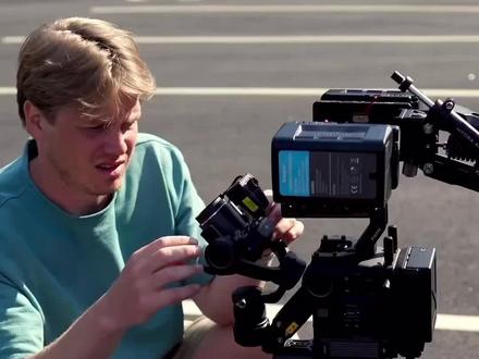 01:03查看AI文稿AI文稿
rigging up as always on the chase car it is the dji ronin 4d connected to the tilta steady cam arm mounted via suction cups and with the hope and a prayer everything stays on and we get some pretty rad shot。 嗯。
247TILTA铁头 01:30
01:30 00:27
00:27


