spaceclaim怎么新建group
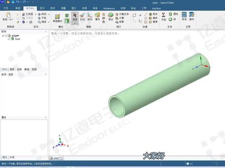
大家好,我们今天学习 space claim 中如何做几何修复。 space claim 包含强大的几何修复功能,首先打开一个几何模型菜单栏,点击修复拼接快框,选出一个区域,点击绿色打勾,就完成了这个拼接的修复。 再点击修复间距,点击绿色打勾自动修复完成。再点击修复缺失的面,点击绿色打勾自动修复完成全部点击之后可以再返回检查一下, 可以看到这里没有提示了,就表示所有问题已经全部修复完成。好了,本次分享到此结束,感谢观看。

粉丝2093获赞8870
相关视频
 01:11查看AI文稿AI文稿
大家好,本视频讲解 ss spaceclaim 软件几何模型的基本操作,比如说单机选择面,三机选择体,菜单栏选择拉动按钮可以放大缩小。实体 菜单栏选择移动按钮,可以按住坐标轴拉动进行直线移动。比如沿着 x 轴移动,按键盘空格键可以输入具体数值。 假设我们要移动 50 毫米,按空格键输入 50, 再按回车键,该实体就成功向 x 轴方向移动了 50 毫米。 还可以点击坐标轴中间的弧线进行旋转,像这样按住拖动即可进行旋转。如果想在额外复制这个零件进行旋转,按住键盘 ctr l 键鼠标在选择旋转坐标轴拖动即可实现。点击菜单栏合并按钮,还可以对这两个零件进行组合。 菜单栏填充的功能是将几何体进行填充成封闭实体。好了,以上就是本节课的全部内容,感谢大家的观看。
169亿道电子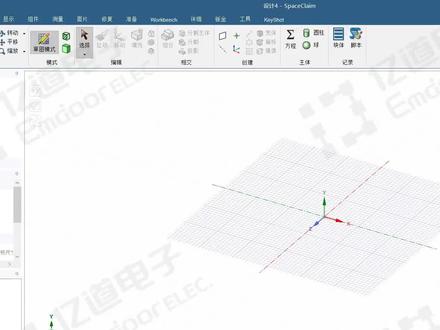 01:20查看AI文稿AI文稿
大家好,今天介绍如何在 spaceclaim 中创建几何模型。首先点击菜单栏文件 spaceclaim 选项,在单位选项选择长度,单位为毫米,选择平面正视图,点击草图, 比如绘制一个矩形,标注尺寸,比如长度两百毫米,回车完成,再设置右边与轴对称的距离是一百毫米,宽度也设成一百毫米, 设置底边与轴对称的距离是 50 毫米。下一步在两边画两个圆,点击剪裁工具,把多余线条给他裁剪掉, 再换两个小圆放在两端,标注尺寸为直径五十毫米,点击结束草图绘制。然后通过拉伸命令拉伸成实体,按住空 格可以修改拉伸长度,比如拉伸五十毫米。我们还可以返回草图模式继续绘制草图,比如在顶面再绘制一个矩形,设置长度宽度都是五十毫米,再设置成轴对称,结束草图绘制。点击拉伸, 向上拉伸是形成一个托台,向下拉伸是切除。使用 spaceclaim 创建己和模型的简单操作就讲解到这里,感谢观看!
397亿道电子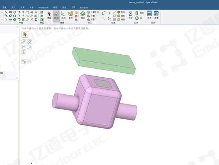 03:45查看AI文稿AI文稿
上节课我们讲到了添加、剪切以及不合并三个命令操作,这节课我们将详细讲解其他主要的功能。 在无任何命令操作情况下,点击一个面,向上拉伸是增加材料,向下是减少材料,当向下减少的幅度超过本身厚度的时候,这个材料就会消失,会完全被剪切了, 恢复到原始状态。如果选择一条线向内拖动,会形成一个到圆角,修改数值可以设置圆角的半径大小,也就是除了拉动面,还可以拉动线。 再返回上一步,来看一下这个旋转命令如何操作。点击旋转,先选定一条线作为旋转轴,再选择一个面 作为旋转对象,沿着这条轴进行旋转,可以按住鼠标左键拉动旋转,也可以输入具体角度,比如输入三十就可以看到选中面沿旋转轴自上而下旋转了三十度。 如果没有精确的角度要求,那么就可以通过鼠标拖动进行旋转,再恢复到初始状态。下面来讲一下脱模,脱模其实和旋转是有相通之处的, 旋转是以线为旋转轴,而脱模是以面作为旋转轴。点击脱模,选择一个面,按住鼠标左键进行拖动, 可以看到这是基于面进行的旋转操作,某种程度上脱模和旋转都可以达到同一种效果。按 esc 再回到初始状态, 这个是扫掠命令,意思就是选择一个面沿着一条线的轨迹进行扫掠。比如我们先选择一个面,再选择一条线作为轨迹, 然后按住鼠标沿着这个轨迹进行拉动。可以看到选中的面随着轨迹的扫掠变成了一个拉伸的几何体,这是直线轨迹,所以对应生成直向拉伸。如果选择一个更复杂的轨迹,比如一条曲线,又会是什么样的效果呢? 比如我们选中这条曲线,按住鼠标拖动,会看到这个面沿着曲线的轨迹逐渐生成一个不规则几何体, 拉伸的弧度和选中轨迹的弧度是完全一致的,轨迹弧度多大,拉身体弯曲的弧度就是多大。 在按 esc 返回初始状态,下面讲解缩放命令,顾名思义,缩放就是操作几合体进行缩小放大。首先点击这个命令,再选择一个基点,最后选择你想要放大的面或几合体。 如果想放大整个几何体,就用鼠标左键在该几何体的任意面上单击三下,再进行拖动,就可以看到整个几何体在缩放变化。 同样的,要是有具体的缩放大小要求,可以输入缩放值,比如输入二十,就可以看到整个几合体放大了二十倍。 在按 esc 返回到初始状态。最后一个命令讲解是直到直到的效果,就是将选中对象指定移动到终点对象,并且只能进行 此方向的移动。比如想拉伸长方体底面正好到下面正方体的顶部,那就先选择直到,再选择长方体底面,再选择正方体顶面, 可以看到长方体底面就正好拉伸到正方体表面了。好了,以上就是 space claim 软件拉伸操作的全部讲解内容,感谢大家的观看。
47亿道电子 10:38查看AI文稿AI文稿
select is one of the most important sections in space claim this is because all of our other tools start with selecting you need to select something to pull select something to move select something to fill so having a good basis of selecting different ways and different techniques would be crucial when working with space glen before we get started as a reminder to rotate the model hold the middle mouse button down to zoom hold control in the middle mouse button and to pan hold shift in the middle mouse button remember if you want to change the way you spin pan zoom this can be done in the options panel under navigation now the basics of select are pretty simple click on something on screen to select it the important thing will be knowing whether you've selected a face versus, an edge versus, a point or a vertex now if you start to select different things and you want to know what's selected you can always look in the bottom middle of the screen to see what's highlighted here and if you hold the control key down you can select on multiple things you can even select on edges faces and vertexes at the same time you'll notice every time you have something selected you can go to this middle of the screen to see what's in your selection in this case i have three faces, two edges and two vertices the same way i add to my selection by holding the control key down i can use this to remove things for my selection by control unselecting things i now have one face, one edge and two vertices the fastest way to remove things from your selection are two different ways you can click in white space anywhere here and it instantly remove things from your selection the second method if i have things selected as i do here is pressing the escape key on your keyboard pressing escape will also remove things from your selection now anne's were moving through the model and selecting things sometimes you want to select unhidden things on a model this can be done by using the mouse wheel on your three button mouse the same way you scroll up and down a web page is the same way you can scroll through the model in space claim it selects straight back through the model to give you all the faces and edges which might be there under your cursor this can be done again scroll your mouse will in or out select what's behind your cursor once you have your cursor there click to select that thing as a reminder if he did go to file space claim options navigation you can set your middle mouse wheel to not query like we've been doing but so that zooms in and out if you do this selection in this option remember to hold ctrl to do a query select also while we're here let's take a look at some of these holes i want to reinforce the difference between faces edges and in this case holes also have axes you'll notice as i hover over these holes axes appear as i hover over the fourth one you'll notice the first axes disappears we provide these temporary axes on the screen to help you select and locate and navigate the centers of holes only three will appear at a time and as soon as you clear your selection by clicking in white space they all go away this will be important though because selecting a face will give you different results in pull and move then select in an edge and selecting an axis we can experiment with what happens when you select on an edge and axis or face with full and move later on lastly while we're here let's look at quick ways to zoom in and out to get our selection if you have a face selected there's a very fast way to zoom in on it by going to zoom zoom extense this will zoom into whatever selected if you have two things selected like these two holes by control selecting them you can zoom extends to zoom into them you'll notice the shortcut for zoom extends is z if i have nothing selected when i hit z it zooms into the complete object this is a very fast way to zoom in and zoom out on different things on the screen now let's get back to selecting a common way in space claim to select multiple things is by double clicking this is similar to the convention and word we would select to put your cursor and double click to expand your cursor to select a single word in space climb double click will give you tangent faces you notice it selects the face here the round and the face on the other side if you double click around it has all of these tangent faces there but you'll notice double clicking around gives you the round chain the reason for this is because that's probably what you'd like to modify either changing the round size to make it larger or smaller possibly removing it or toggling it to a chamfer we've tried to change the selection to make it easier to work with also notice when double clicking faces that are here you can double click edges double click in an edge will grab you that tangent edge chain however, what if you wanted a different edge loop like the loop around this face simply double clicking a second time will toggle to a second edge loop double clicking a third time will toggle to the third edge loop so double clicking will toggle through the different possible edge loops that are there in the case of this face if there are only two edge loops it will only toggle between the two available this is a fast way for grabbing edges around a model one of the most common ways to select things in space claim is via a box select it's very useful to selecting a lot of geometry holding down with your left mouse button will let you draw a box on screen to select everything that encompasses it the key with box selecting is to pause to see what's in your selection right now i have the axe if i make bigger i have all the letters and a few of these holes as soon as i let go of my mouse i can see what's being selected now the key with box selecting is that there's a difference between box selecting from left to right versus right to left if i go left to right only things that are entirely in my box gets selected and we operate under smart selection hierarchy where if i start my box and there's only edges in my box only edges get selected as soon as faces enter my box faces begin to be selected if you like to control this you can look at our selection filter on the bottom right hand corner of the screen to get exactly what you need most of the time you'll want a box like from left to right as i'm doing here and paul is to see what's in your selection the other method is to box like from right to left box selecting from right to left will select anything that crosses your box notice i get a lot more geometry really quick when i'm box selecting from right to left box selecting from right to left is commonly used when changing the color of objects selecting any piece of a model to hide or to show or from moving things into a different layer for precise selection it's much more common to box select from left to right and remember if you pause for a second, you'll be able to see exactly what's in your box to make sure that's what you'd like to grab i'm going to hit z one more time to zoom to the extents the last thing we'll look at is how to quickly select a solid now you'll notice it says here we can click an object double click to grab an inch loop or triple click to select a solid remember the status messengers are helpful to let you know what a particular tool does or what the tool is asking you to do triple clicking to select a solid simply involves you to click click click if i hover over the face and i click click click you'll notice instead of having faces selected i have one single body selected it's the same as a double click except we have one more at the end so click click click select the body now some people don't like selecting by triple clicking and that's fine we have a lot of other techniques for selecting bodies first off box selecting the entire model we'll select that body because all of the faces the same time are selected so it automatically up selects to the body if you're not in a situation where box selecting makes sense also selecting from the structure tree is a valid way for grabbing that body whether i triple click select the body in the structure tree or box select all of them give me that body selected so i hope you've seen different ways to select on objects and remember it's going to be critical to know whether you have curves edges, faces, surfaces or vertexes selected, so please check the bottom middle to your screen so you can see what's actually in your selection before you make a pull move fill or combine operation thank you for watching。
13亿道电子 08:24查看AI文稿AI文稿
过过去,问你在哪里,和谁在一起,怎样的心情?是什么天气啊,该怎么开始滑梯?我好怕伊我出去走不了你的主意故事不能继续。 凌晨三点半的老街,雨滴打湿了青苔,窗外朦胧的雨声,悦耳的别墅,心态受到 觉得芭蕉不放慢,体会这个季节, 想起歌词说出去,我把你讲出 还没收到你的消息, 不肯拨过去,问你在哪里,和谁在一起,怎样的心情,是什么天气啊,该怎么开始滑梯,我好怕一晚出去走不了你的主意故事不能继续 的创意从哪听来我记住你模糊的笑曲, 满不自觉的芭蕉不放慢,体会这个词,一切都要 怎么还没收到你的消息,那时我也不肯泼过去,问你在哪里,和谁在一起,怎样的心情,是什么天气啊,该怎么开始滑梯,我好怕意外出去,躲不了你的主意故事不能继续。 凌晨三点半的老街,雨滴打湿了青苔,窗外朦胧的雨声,悦耳的别墅, 邀约这个创意,从那听来,我心中你模糊的笑曲,像我 觉得芭蕉不放慢,体会这个季节多 当着歌词说出去,我怕你假装听不清。
124科技一言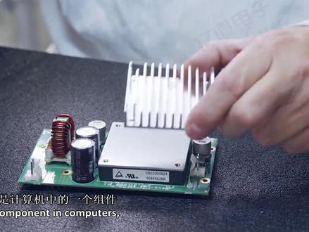 08:28查看AI文稿AI文稿
in this session, we will analyze how to build a model of heat sink? what is a heat sink a heat sink is a component in computers that is used to reduce the maximum temperature reached by the cpu, the metal fins provide increased surface area and this improves the amount of heat drawn away from the cpu and exchanged with the surrounding air so how can we build a model of this first let's analyze the shape and plan how to build the model? this is a technical drawing of the model it is a typical sketch used by engineers to provide the information on the dimensions of objects in real life, we can use these drawings to guide our building process what you see here are views of the same object from the top side front and so on the numbers tell us the measures of the different parts so that we can always replicate the original model i know this can be a little confusing but don't worry we'll explore as we go and understand how to use it to have the right dimensions for our model look at the drawing the base of the heat sink is rectangular we can sketch it and use the pull tool to easily created once we have the base we can build all the other features easily the second step can be the creation of the four holes for the mounting screws they are equally spaced from the sides and have the same diameter we can create one using the pull option and then copy and move it to create the other ones this would reduce the number of operations we need to perform defends all look the same right, they're all the same size straight, equally spaced and if we look at them from the top, they have a rectangular shape, we can sketch a rectangle on the base and copy it as a pattern so that we can keep the same dimensions and spacing among the fins then we can pull all of them up to complete the model all right, we've got our plan the steps are creating the base first, then the holes and the fins and also we planned how to make each element let's get started open a session of space claim first set the plan view select the rectangle, sketch tool and then activate define rectangle from center this window shows you all the additional options for the tool you are currently using click in the center of the drawing area and move the mouse as you can see in the drawing the base is one hundred thirty millimeters, wide and fifty millimeters high in order to draw a precise sketch you can type those values and use the tab key to move among the dimension fields press enter return to the three d view and press h for the home view the pull option is already activated so select the rectangle the drawing shows that the base is five millimeters thick suppress the spacebar and enter five millimeters we've completed building the base of the model now let's create the holes select the top face of the base set the plan view and enter sketch mode select sketch circle then hover the mouse over the top left corner of the base and tap the shift key on the keyboard as you move the mouse the distance from the corner is displayed place the center of the circle at five millimeters from the left edge and negative ten millimeters down from the corner press enter this identifies the center of the first hole shown in the drawing set that diameter as five millimeters and press enter go back to three d mode and press h to go to the home view select the face of the circle and pull it down this generates a through hole all the way through the base of the model click, the move tool and then select the face of the hole, press the control key and select the handle matching the x direction click and drag to create a new hole and then type one hundred twenty millimeters to place the new hole in the correct position while holding control select both holes, then click and drag the y handle to duplicate them answer a value of thirty millimeters and press enter we've created the four mounting holes let's move on to modeling the fins select the upper face of the heat sink set the plan view and enter sketch mode select sketch rectangle and use the shift key to define the position of the first fin from the top left corner of the heatsink base move the mouse right along the upper edge by nine point seven five millimeters create a rectangle five point, five millimeters in width and fifty millimeters in height this is the base of the first fin click select then click and drag a box from left to right to select the rectangular profile select the move tool and activate the create patterns option here on the left select the arrow matching the x direction and drag it then set the number of instances to eleven and the distance between them to ten point five millimeters you can switch between the dimension fields using the tab key now switch to three d mode by pressing the letter d on the keyboard select the first rectangular face and then go to the selection tab beneath the structure tree choose the option faces with same area as you can see now all the rectangles in the pattern are selected activate the pull tool then press the space, bar and enter seventy millimeters as the fin height we've now completed the model let's explore some additional features using this model first, let's see how we can make it look more realistic click and drag a box around the model then go to the display tab click the color swatch to expand the color menu, then set the color to dark gray we can modify the way the model is shown using these options here shaded gives a realistic look to the model and enhanced shaded makes it look even cooler by adding some lighting effects and shadows the wireframe, hidden line and hidden line removed options are useful to better visualize complex models this option allows us to change the rendering styles we can set it to be metal plastic and even change the level of glossiness using the finish option the next option down allows us to toggle the transparency if you want the ultimate realistic look you can also remove the lines from being displayed by deselecting solid from the edges options now it looks like a real metal piece last, let's discover a few additional options we discussed sketch mode and three d mode, but there's a third mode here that's the section mode and it lets us visualize a cross section of the model select this option and select a horizontal plane by hovering the mouse on any horizontal face and then clicking it let's say that now we want to change the plane because that was not the correct one click the new sketch plane button and choose a vertical plane like this one now click on move grid and drag the arrow to move the grid and see the cross section of the object remember to save the file before closing congratulations you've just completed the design of the heat sink。
56亿道电子 01:46查看AI文稿AI文稿
哈喽,大家好,我是黑白助理佳佳。如果你想用一个主机连接有两个显示器,那么最简单的方法就是在电脑中打开设置系统显示,找到多显示器设置, 将屏幕二设置为扩展显示即可。如果你选择了复制显示,两个显示器是同样画面。当然,如果你没有两个显示器的情况下,在 windows 系统中最简单的就是按下 v 加 ctrl 加低键, 新建一个全新的屏幕,按下 wifi 键即可选择对应屏幕。你还可以使用手机变成电脑的第二显示器, 使用 spasc, 这是一款免费的软件,在官网下载 pc 端启动后让手机和电脑连接在同区域网下,手机端下载安装 sps, 成功连接之后就可以看到移动设备已经变成第二屏幕,点击设置可以手动设置,传输的画面质量和分辨率 需要根据设备的流畅进行设置。接下来我们来体验一下吧。 经过测试,手机播放声音只会从电脑发出画面,卡顿效果还算能接受。关注黑白办公微信号,回复屏幕,获取下载链接。
270黑白小技巧 07:18查看AI文稿AI文稿
电传动结构 states claim 管理组建大家好,今天给大家分享一个在 speciclam 中对电传动结构进行一个组建管理。首先在 word 伴视平台下新建一个 geometre, 这里我们右键选择导入几何模型, 在此右键选择在 spicy climb 中编辑几何模型,进入到 spicy climb 中,这是几何模型,包括这样一个主动列轮,主动列轮以及链条。整个模型的零部件比较多,在分析之前呢,就要对这个组件进行一个管理,可以通过这样一个框选的方式 排序,对我们的组件进行一个分组。首先对于这个虫洞链轮,可以从右向左对他进行一个框选,接着我们在这里右键选择,移动到新的组件中,给他这样一 个从动链轮的名称。对于这个主动链轮,同样是从右向左进行一个框选,接着我们把它给移动到新的组件中,组件的名称为这样一个主动链轮。 接着我们把这个从动链轮与主动链轮这两个组件进行一个隐藏,剩余的就是链条的一个结构了。在这个链条的结构中呢,他又包括 这样一个外链板与这样一个内链板,以及滚子,还有中间的套筒等结构,所以说它包括的零件是比较多的。在这里可以 通过这样一个框选,选中对应的一个组件,把它们放在对应的一个组件中。在这里我们从右向左首先框选这个外链板,按住 ctrl 键,同样是从右 向左选择左边的这一层外链板,再次进行一个选择,选择完成之后呢,我们右键把它们移动到新的组件中去,这个组件的名称就叫外链板。 把这个外链板进行隐藏,剩余的这个结构呢就是我们的内链板以及这样一个滚子所包含的这些实体结构。 还是同样的一个方法,从右向左,首先框选这个内列板,接着按住 ctrl 键,从右向左,再选择左边的这一层内列板, 选择完成之后,把他们移动到新的组件中去,这个组件的名称就叫做内链板。再把内链板进行一个隐藏,剩余的就是一圈的滚子框,选,把这些滚子移动到一个新的组件中,这个名称 就叫做滚子。完成他的一个组件的管理之后呢,回到目录处的最上层,在这里我们右键选择删除空组键,剩余的就是这些这个同动链轮,主动链轮以及这样一个外链板, 内链板还有他的滚子,但回到这里可以以这个从头猎人为对象,把这个从头猎人组件给他打开,打开这个组件之后呢,对这个组件进行一个微小特征的去除。首先的话我可以看一下他包括一个胶钉 建槽,传动轴与同动链轮,可以把这样一个消钉与零件给他删除掉,接着我们把路轴给他隐藏,在这里,可以在准备菜单栏下面选择这个移除面,移除他的一个圆角以及 他的一个倒角,点击这个绿色的对号,把他们给移除掉。同样的操作,按住这个 ctrl 键,同时选择多个这样一个微笑特征进行移除。 对于这样一个齿面上的这样一个圆角,我们也可以把它们给移除掉。 对于这个螺钉的微小的孔,可以通过设计菜单栏下面找到拉动命令, 首先点击这个安装孔的一个内孔,在这样一个方框这里输入零,点击回车,完成螺钉孔的一个填充。 在这个箭槽的位置,首先可以选择箭槽的上底面,接着我们选择拉动到一个平面,再选择这个圆柱面,完成这个箭槽的一个填充, 填充完成之后,再把传动轴给他显示出来。准备菜单栏下面找到这样一个移除的微小面,选择这些微小的一个面,按住 ctrl 键选择他们,点击对号移除 另一端,我们同样的按住 ctrl 键,然后把它们给移除掉。 对于箭槽内部的这些小的一个导角,也同样是按住 ctrl 选中这些导角,同时把它们给移除掉, 就是两端的一个吹孔,也可以通过这种方式进行一个移除。 对于这个箭槽,我们在设计菜单的下面找到这样一个拉动命令,选择这个 箭槽的底部,再选择拉动到某一个平面,再选择这个圆柱面,完成这样一个箭槽的填充。对于这样一个沉孔两端的一个沉头孔,在这里我们可以同样选择孔的一个底面,然后选择拉动到某一个平面,选择这个端面,完成这个沉头孔的 填充,完成这个轴的胳膊小特征的去除,再显示出总动齿轮,总动轮显示出来之后呢,他们之间呢需要进行共享拓扑,可以在乌克半尺太大栏下面找到共享, 找到这样一个共享拓扑,软件会自动查找他们所能够进行的一个共享的面与边线,点击对号完成他们之间的一个拓扑的共享,实现他们的一个共结点的操作。在下面找到这样一个 um, 点击他的一个叉号,把它给关闭掉,回到整个的模型中。再以这样一个外链板为例,打开他的一个组件,在这里我们可以看到他包括众多的这样一个链接,包括很多小的链接, 这些链接呢,他是保存在同一个组件下面的,同样采用这样一个框选的方法,把这些小的链接给他们组成各自的一个组件, 隐藏这个小的组件,可以通过对应的方法把这些小的链接移动到各自的一个组件中去。 之后呢,可以看到每一个组件保存了一个完整的链接。接着我们可以再次打开这样一个组件,在这一个链接中 进行一个微小特征的去除,或者说进行共结点,在共享这里找到共享,点击这个绿号,完成他的一个拓坡的共享,实现他的一个共结点。完成共结点之后呢,再把这样一个小的组件给他关闭掉,回到他整个的组件中,再把这个组件进行一个关闭, 再次回到整个模型的一个组件,在这里我们就可以找到外链板,把它给展开,可以看到它内部是包含这些十九个外链板的子组件的,按照同样的方法,可以对这样一个内链板进行对应的这样一个组件的管理,今天我们的分享就到这里。


![[三角符文第四章]
全流程(除mike战)
-第三部分- #三角符文 #三角符文和平线 #Deltarune #三角符文第四章](https://p9-pc-sign.douyinpic.com/image-cut-tos-priv/48597e88935820fc79863b929aa6beda~tplv-dy-resize-origshort-autoq-75:330.jpeg?lk3s=138a59ce&x-expires=2079180000&x-signature=Rpm041jg6xgLYTpDhdJivyq7fvE%3D&from=327834062&s=PackSourceEnum_AWEME_DETAIL&se=false&sc=cover&biz_tag=pcweb_cover&l=20251122225655C5F5E8C7387DF3931C71)
