ansys只安装spaceclaim
大家好,本次给大家介绍 ansis space kim 波尔计算的操作方法。在接近几何注意的时候,尤其是尸体模型经常会遇到波尔计算求两个相交实体之间的并级交集,还有差级等等要运用到波尔计算的操作。波尔计算就在这个设计这捆绑组合的工具箱里 点一下,假设要求它俩的并级操作,先选中一个,然后选右边这个 mark, 再选入另外一个空八柱三记下,这个时候它俩就合并成一个整体了, 并且它也是没有任何干涉部分,没有交集车交下。那如果我们要进行切分操作,用六圆球把这个角切掉,那我们就先选对切根物件切,工序不变,再选择球体点一下,快点,这个角就被球一分为二了。把球体隐藏一下,可以看到这个已经是单独的一个体,把它隐藏一下, 这时候它就被一分为二了,并且这个球体也是被保留下来了。那如果说你不想保留这个球体,可以取消勾选 kartter, 然后被切割切工具,那么这时候它一分为二了,球体就可以自动删除掉,如果说你也不想要这一部分,手动比例的键删除就可以了。还有一种就是要求这个加急的话,把多余的这一部分把这部分删掉,像三级只保留这一部分就行了。荣正既要切割也要都保留,那么就采用 kart 这样把它切分一下就行了,而且这个时候球体是完整的,被切割 的物件就被一分为二了,这个是通用的不认算操作。 switch can 还提供了另外一种叫刻印的方法,就是把由于块体相交的胶线刻印到实体表面上,还是用了 make cap 这些功能。我们先选中被刻印的块体,再选中刻印的球体, 把球体隐藏,两个物体相交的胶线就被刻印到了实体表面上,并且它没有被一分为二三 g, 可以 看到它还是一个完整的体,只是多了这三条线,这个就是过尔运算胶线刻印的功能。大家如果觉得有用的话,可以点个关注点个赞,感谢大家的支持!

粉丝1447获赞3000
相关视频
 01:08查看AI文稿AI文稿
大家好,今天介绍 space claim 如何组装零件,现在打开的是有三个零件的一个组装体,首先我们点击组件菜单,然后选择想要移动零件的一个面,在选择装配零件中,需要和刚才选重面贴合的面点击对齐, 此时这两个面就移动到同一平面了,然后再分别选中这两个零件的顶面,再点击对齐,这样两个零件的顶面就保持在同一水平线上。最后再选择剩余的一个侧面,点击对齐。 好了,这样三个面分别对齐后,两个零件就组装好了。另外一个零件也是同样的操作,选择需要移动零件的一个面,在选择装配零件中,需要和刚才 选中面贴合的面点击对齐,然后再分别选中这两个零件的顶面,点击对齐,最后再选择剩余的一个侧面,点击对齐。好了,这个零件也组装好了。本次分享到此结束,感谢观看!
46亿道电子 08:28查看AI文稿AI文稿
in this session, we will analyze how to build a model of heat sink? what is a heat sink a heat sink is a component in computers that is used to reduce the maximum temperature reached by the cpu, the metal fins provide increased surface area and this improves the amount of heat drawn away from the cpu and exchanged with the surrounding air so how can we build a model of this first let's analyze the shape and plan how to build the model? this is a technical drawing of the model it is a typical sketch used by engineers to provide the information on the dimensions of objects in real life, we can use these drawings to guide our building process what you see here are views of the same object from the top side front and so on the numbers tell us the measures of the different parts so that we can always replicate the original model i know this can be a little confusing but don't worry we'll explore as we go and understand how to use it to have the right dimensions for our model look at the drawing the base of the heat sink is rectangular we can sketch it and use the pull tool to easily created once we have the base we can build all the other features easily the second step can be the creation of the four holes for the mounting screws they are equally spaced from the sides and have the same diameter we can create one using the pull option and then copy and move it to create the other ones this would reduce the number of operations we need to perform defends all look the same right, they're all the same size straight, equally spaced and if we look at them from the top, they have a rectangular shape, we can sketch a rectangle on the base and copy it as a pattern so that we can keep the same dimensions and spacing among the fins then we can pull all of them up to complete the model all right, we've got our plan the steps are creating the base first, then the holes and the fins and also we planned how to make each element let's get started open a session of space claim first set the plan view select the rectangle, sketch tool and then activate define rectangle from center this window shows you all the additional options for the tool you are currently using click in the center of the drawing area and move the mouse as you can see in the drawing the base is one hundred thirty millimeters, wide and fifty millimeters high in order to draw a precise sketch you can type those values and use the tab key to move among the dimension fields press enter return to the three d view and press h for the home view the pull option is already activated so select the rectangle the drawing shows that the base is five millimeters thick suppress the spacebar and enter five millimeters we've completed building the base of the model now let's create the holes select the top face of the base set the plan view and enter sketch mode select sketch circle then hover the mouse over the top left corner of the base and tap the shift key on the keyboard as you move the mouse the distance from the corner is displayed place the center of the circle at five millimeters from the left edge and negative ten millimeters down from the corner press enter this identifies the center of the first hole shown in the drawing set that diameter as five millimeters and press enter go back to three d mode and press h to go to the home view select the face of the circle and pull it down this generates a through hole all the way through the base of the model click, the move tool and then select the face of the hole, press the control key and select the handle matching the x direction click and drag to create a new hole and then type one hundred twenty millimeters to place the new hole in the correct position while holding control select both holes, then click and drag the y handle to duplicate them answer a value of thirty millimeters and press enter we've created the four mounting holes let's move on to modeling the fins select the upper face of the heat sink set the plan view and enter sketch mode select sketch rectangle and use the shift key to define the position of the first fin from the top left corner of the heatsink base move the mouse right along the upper edge by nine point seven five millimeters create a rectangle five point, five millimeters in width and fifty millimeters in height this is the base of the first fin click select then click and drag a box from left to right to select the rectangular profile select the move tool and activate the create patterns option here on the left select the arrow matching the x direction and drag it then set the number of instances to eleven and the distance between them to ten point five millimeters you can switch between the dimension fields using the tab key now switch to three d mode by pressing the letter d on the keyboard select the first rectangular face and then go to the selection tab beneath the structure tree choose the option faces with same area as you can see now all the rectangles in the pattern are selected activate the pull tool then press the space, bar and enter seventy millimeters as the fin height we've now completed the model let's explore some additional features using this model first, let's see how we can make it look more realistic click and drag a box around the model then go to the display tab click the color swatch to expand the color menu, then set the color to dark gray we can modify the way the model is shown using these options here shaded gives a realistic look to the model and enhanced shaded makes it look even cooler by adding some lighting effects and shadows the wireframe, hidden line and hidden line removed options are useful to better visualize complex models this option allows us to change the rendering styles we can set it to be metal plastic and even change the level of glossiness using the finish option the next option down allows us to toggle the transparency if you want the ultimate realistic look you can also remove the lines from being displayed by deselecting solid from the edges options now it looks like a real metal piece last, let's discover a few additional options we discussed sketch mode and three d mode, but there's a third mode here that's the section mode and it lets us visualize a cross section of the model select this option and select a horizontal plane by hovering the mouse on any horizontal face and then clicking it let's say that now we want to change the plane because that was not the correct one click the new sketch plane button and choose a vertical plane like this one now click on move grid and drag the arrow to move the grid and see the cross section of the object remember to save the file before closing congratulations you've just completed the design of the heat sink。
59亿道电子 01:20查看AI文稿AI文稿
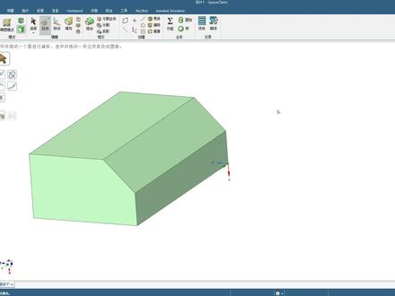
大家好,今天介绍如何在 spaceclaim 中创建几何模型。首先点击菜单栏文件 spaceclaim 选项,在单位选项选择长度,单位为毫米,选择平面正视图,点击草图, 比如绘制一个矩形,标注尺寸,比如长度两百毫米,回车完成,再设置右边与轴对称的距离是一百毫米,宽度也设成一百毫米, 设置底边与轴对称的距离是 50 毫米。下一步在两边画两个圆,点击剪裁工具,把多余线条给他裁剪掉, 再换两个小圆放在两端,标注尺寸为直径五十毫米,点击结束草图绘制。然后通过拉伸命令拉伸成实体,按住空 格可以修改拉伸长度,比如拉伸五十毫米。我们还可以返回草图模式继续绘制草图,比如在顶面再绘制一个矩形,设置长度宽度都是五十毫米,再设置成轴对称,结束草图绘制。点击拉伸, 向上拉伸是形成一个托台,向下拉伸是切除。使用 spaceclaim 创建己和模型的简单操作就讲解到这里,感谢观看!
413亿道电子 09:42查看AI文稿AI文稿
in this section, we're going to take a look at imprinting and splitting faces i'm going to open up by a part called imprint and split face and open it into space clamp splitting faces is really helpful so you can apply different meshes boundary regions or supports on just a portion of a face instead of the entire face that's there in this section we're going to be looking at three main tools for doing this under the intersex group we'll be looking at the split face tool which lets you select a face and split it we'll be looking on our sketch tool which is face curve this lets you free forms sketch on a face and the third tool under the prepared tool is going to be our imprint tool this takes two solids as long as the faces are coincident it imprints the edges of one face onto the other face let's start by looking at the least precise technique and that's going to be our face curve tool when i click on this under sketch notice it lets me start selecting on the model and start sketching as soon as i click on a face it adds a point or a node to that and i'm essentially sketching a spline on a face now you can switch between faces that are there and when you click the starting point it makes this complete spline now you can drag on these points and reposition them on your model but notice if you go too far if it gets too crazy it might not actually be able to make this spline and then it's going to show you that it doesn't exist anymore so if you want that to be a little bit crazy you'll have to have more spine points that are driving it whenever you're ready you're finished or you'd like it you can click the check mark on your screen or you could hit the enter key on your keyboard that splits these three faces on the model so now you could apply this for maybe a drop test you might want to split this region up you just might want a higher mesh configuration con duration on this area or maybe we're applying heat to only a certain portion of the model notice this technique is probably the least precise of the techniques and methods i'm going to show you but it lets really quickly split a face the next tool we're going to be looking at is going to be the split face tool under the intersect group now with the split face tool you're going to have a lot of tool guides that are there and let's look at these tool guides one at a time the first tool guy that you'll have on the model see i want to work on this face and i'm going to click that on my model this first tool is called the uv cutter point so we start off by clicking the face we want to split and then selecting another uv to cut it with now as i hover around edges you'll notice that i get a distance and a percentage so if i wanted to cut this face in half along this edge i could type in fifty percent then we'll put our cutter line right in the center and this splits into two faces of the same area the next face that we can split with the next tool guide is called perpendicular cutter points if i choose that say i want to cut this top base i have to hover over an edge and whenever edge i hover over it's going to make a cutter that's perpendicular to that edge as i move my cursor around this round edge it's always cutting towards the center it's always making this cutter perpendicular to the edge i'm hovering over the next one is two cutter points so if i wanted to cut this model from this point to the one on the other side of the model notice, i can click to snap to this point and my second click will draw a straight line between those two points so if i want to click on our second point here i can split this face into two pieces to apply a better mesh there i'm going to undo once that's there i'm going to show you another thing as i'm splitting this technique that i use a lot to make sure that i'm actually on the end point of it is to snap into type in a value because you can split a face on a certain one edge and i can click in the center of the model and it's not going to split it all the way through which is going to imprint a liner and edge on that face so to make sure that you're always going from point to point notice we're always working with a percentage of the edge i could type in zero percent, which make sure that i'm starting at this point if i hover here notice i'm at ninety two ninety three ninety four if i type in one hundred percent i'll snap right to the other side make sure that i split this into two sections lastly, let's take a look at another way to split this model what i'm going to do is i'm first going to turn off everything except the base by turning them off in the structure tree let's say i want to split this center face it's here the last tool is select cutter face this since we take a face and cut it with another face notice this face extends outward and lets me cut this center face by this bottom face cuts it straight across and splits it into two sections this is really useful for simply extending the face and slicing with another face in the model now the other thing that's really useful with these tools that i'm showing you is that you can split multiple faces at the same time for instance remember this first split that i made fifty percent along that edge what i could have done is i could have selected one control select two control selected three faces and split them at the same time so if i split this twenty five percent along this edge i would split all three faces at the same time to nicely isolate that so i apply a nice mesh to this area region now there's one more thing i want to show you with our splitting faces i'm going to use the imprint to do that i want you to reverse this turn off the base and turn on the remaining components that are there so turn on bolt bearing and shafts and go to the imprint tool under the prepared tab what this does is it finds the different areas where an edge on one face intersects with a face on the other face i'm going to escape out of this to show you if i hide this bearing notice there is no lines or imprints on this green face by turn the bearing back on and click imprint what it's doing is imprinting the edge of this blue face onto the green one now the what this will let me do is let me create a continuous mesh or just have the same area faces on each model so just to show you if i go back to the select tool this green part here has been split into different sections and if i go to the measure tool under the measure tab area of this face is fifty one point, two seven five five millimeters if i show the bearing the area of this face is fifty one point, two seven five five millimeters so what it does it creates the exact same face on both models so you can have a really nice between them i hope you've seen three different methods of splitting faces by using face curves sketching directly on a face using our split face tools to split faces by uv curves perpendicular lines, two cutter points and also the extended faces and also our imprint tool thank you for watching。
24亿道电子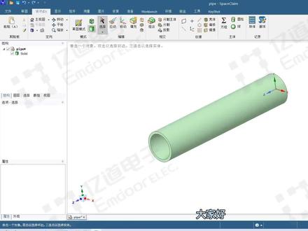 01:11查看AI文稿AI文稿
大家好,本视频讲解 ss spaceclaim 软件几何模型的基本操作,比如说单机选择面,三机选择体,菜单栏选择拉动按钮可以放大缩小。实体 菜单栏选择移动按钮,可以按住坐标轴拉动进行直线移动。比如沿着 x 轴移动,按键盘空格键可以输入具体数值。 假设我们要移动 50 毫米,按空格键输入 50, 再按回车键,该实体就成功向 x 轴方向移动了 50 毫米。 还可以点击坐标轴中间的弧线进行旋转,像这样按住拖动即可进行旋转。如果想在额外复制这个零件进行旋转,按住键盘 ctr l 键鼠标在选择旋转坐标轴拖动即可实现。点击菜单栏合并按钮,还可以对这两个零件进行组合。 菜单栏填充的功能是将几何体进行填充成封闭实体。好了,以上就是本节课的全部内容,感谢大家的观看。
192亿道电子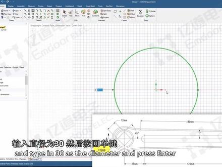 10:53查看AI文稿AI文稿
in this session, we will see how to build a model of a bite crank? what is a bite crank? it's one of the components of a bicycle one end of the bike rank is connected to this bracket while the other end is connected to the pedal when the bicycle rider presses their foot on the pedals, the bike crank revolves and causes rotation of this bracket wheel, which drives the chain this in turn drives the rear wheel, so how can we build this bike crank model? let's analyze the shape first and plan how to build the model first, we'll take a look at the technical drawing looking at the views we can consider the bike rank as a rectangular shaped rod with both ends having a circular shape, so we can first sketch the base using dimensions from the top view and then pull it to create the base model of the crank once, we have the base model we can create the holes at both ends notice that the square shaped hole on the left side and the circular hole on the right side cut through the entire thickness of the crank so to reduce time and the number of operations you can first create this square and circle sketch and pull both the faces to create the holes afterwards you can sketch the circle around the square shaped hole and pull it downwards to create a cut finally we need to create the slot at the center and add chamfers to the edges of the crank looks like we have our plan first, we'll create the base and the holes and finally the slots and chamfered so let's get started open a new space claim session set the plan view by pressing the letter v on your keyboard and sketch the base shape on the xy plane, we'll first sketch the circular ends of the crank select the circle sketch tool click the world origin to define the center of the circle, then move the cursor away from the center and type in thirty as the diameter and press cancer the first circle representing one end of the bike rank is created next we need to create one more circle at the other end the drawing shows that this circle is located at one hundred seventy millimeters from the circle sketch that we just created with the circle sketch tool still active place the cursor at the origin, but don't click hit the shift key to activate the reference dimensions move the cursor slightly towards the right without exiting the first circle and specify the horizontal reference dimension as negative one hundred seventy millimeter and press enter make sure that the other reference dimension remains at zero the center of the circle is now defined at a distance of one hundred seventy millimeters from the origin move the cursor away from the center and type in twenty five millimeters as the diameter and press enter the circle representing the other end of the bike crank is created we now need to connect the two circles from the drawing it can be seen that the base shape is symmetric about the horizontal axis so instead of creating the same sketch lines on both sides we can take advantage of the mirror functionality within sketching select the construction line tool and create a construction line of any length along the horizontal red axes press s to activate the select tool then right click on the construction line and select set as mirror line this will make the construction line, a mirror line and automatically create mirrored entities of any sketch that will be created above or below the construction line let's go back to the drawing if we look closely at the top few, we can see that there is an inclined line making an angle of one degree with the horizontal axis the ends of this line are connected to arcs and these arcs are connected to the circles that we've sketched the arc dimensions are not provided however, it can be understood that these two arcs are congenitally connected to the inclined line and the circle so, if we can get the dimensions of the incline line, we can create the tangentially connected arcs easily using the tangent arc tool, we can also see that one end of the inclined line is located twenty millimeters to the left and ten millimeters up from center of the smaller circle also the length of this line is one hundred thirty millimeters so let's create it select the line sketch tool over the cursor at the center of the twenty five millimeter circle and press the shift key move the cursor left and specify a horizontal dimension twenty millimeters and a vertical dimension of ten millimeter then presenter the start point of the line is now defined now let's create a line with the one degree incline and a length of one hundred thirty millimeters notice that its mirror entity will also get created now click the tangent arc tool in the toolbar select any end point of the line to start creating a tangent curve next move the cursor over the nearby circle until you see a tangent constraint appearing this is indicated by two small parallel lines near the cursor click on this location to complete the arc create another tangent curve at the other end notice that the tangent curve also gets created on the lower side of the horizontal axis we now have our outer sketch ready, but we need to remove the intersections of the two circles in order to create a single closed select the trim, away tool and click the inner circle sections to delete them the sketch is now ready to be converted to a solid model return to three d mode by pressing d on the keyboard and then press h to go to the home v click the surface notice that a mirror plan has been created select this plane and press the delete key to delete it now start the pull tool and select the surface profile, click and drag up and specify a thickness of ten millimeters we've now finished building the base of the model let's create the two holes which are passed through the crank select the top face of the base and go to the plan view by pressing v on the keyboard go to sketch mode and select the circle tool over the cursor over the circle on the right side of the crank and locate the center point place a twelve millimeter diameter circle here next we need to create this square shaped hole notice that if we use the rectangle tool the rectangle will be aligned along the x and y axis however, the drawing shows that the edge is at forty five degrees to the center axis one way we can do this is to use the line tool create four lines at forty five degrees a better way is to use the rectangle tool and create the square shape then switch to three d mode create the hole and rotate the hole by forty five degrees so let's do that activate define rectangle from center and place the rectangle on the world origin create the rectangle that's twelve millimeters by twelve millimeters and press enter return to three d mode and press h for the home fee the pull option is already activated hold ctrl and select both the square face and the circular face at the opposite end of the crank, then click and drag to cut holes through the entire thickness of the crank the next step is to rotate the square shape hole select the top face and go to the plan view start the move tool then click and drag a box around the square at the bottom right of the window you should see that four faces are selected select the blue drag handle press the spacebar and enter forty five this completes the rotation of the square hole next we need to create a circular hole around the square shape hole select the top face again and go to sketch mode start the circle tool and place a twenty millimeter circle at the world org return to three d mode and press h on the keyboard to go back to the plan view the pull tool should already be active select the face around the square the front view of the drawing indicates that this hole has a depth of three millimeters so press the spacebar and enter negative three then press center click select in the toolbar to exit the pull tool notice that a square phase is also created select this and delete it using the glee key on your keyboard。 the next step is to create the slots at the center a more efficient way to do this is to create a hole and then pull its center axis to create the full length slot see how we can do this select the top face again and switch to sketch mode go to the plan view then click the circle tool and place an eight millimeter circle eighty five millimeters to the right of the origin this is half the distance between the two holes start the pull tool and select this circular profile hold the circular face downward negative two millimeters with the pull tool still active zoom in and move the mouse cursor over the cylindrical face of the hole select the center axes and enable the option to pull both sides from the options panel in the front view of the drawing, we can see that the slot should be one hundred twenty millimeters long press the space bar and answer a value of one hundred twenty then bresenter repeat these steps on the other side of the crank to create a similar slot the last step is to create the chamfer double click any outer edge to select the entire edge loop once selected select the champ for option from the panel on the left side of the window and press the space bar specify a value of one point, five millimeters and press center repeat this process for the opposite side of the crank arm and the circular edges located on the top face we now have the final model of the bike crank we can improve the look of the bike crank by modifying the color and the rendering options select the body and change the color from the display tab in the color panel then select the graphics button and choose enhance shaded the crank arm is going to be made of metal so we can try to give it a shiny appearance select the body again from the structure tree and expand the rendering style menu select metallic then go back to the menu and set the finish to high gloss finally we can shut off the display of solid and tangent edges select the edges menu and clear the selection next to tangent and solid we've now finished designing the bike crank。
32亿道电子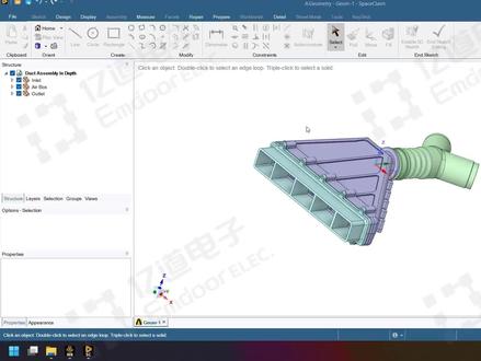 25:05查看AI文稿AI文稿
现在我们开始讲述一下 spaceclam 怎么把这样一个管路系统 抽取计算率,然后并且做一些包括像边界条件分组啊等等基本操作。 首先这是一个呃管路的,这是一个管路的一个装配体, 大概就是这样子,在左侧的结构数上面分了三个部分,分别是入口段就是这个绿色的部分,空气腔 中间的紫色部分,然后出口段外面的外面的这一段,呃青青色的部分,然后这这三段呢构成了一个完整的空气呃一个完整的管路装配体。 首先第一步啊,从个人习惯来说,首先第一步是对他做一些 复制的复制和备份,相当于把原始的几合体把它备份备份出来, 然后在装配速度中把这几个全部都 放在这个原始几何题里面,然后另外呢就再训练一个。呃,第二个的作用就是把 这些原始的几合体做一些修修复讲话等工作之后把它复作为存放的地地方,然后原始的几合体就不要动了,这个里面 三次点击某一个实体的表面,然后就可以把它选中,然后我们可以用鼠标右键点击 copy 复制,然后再在空空白的地方点击 pass 的粘贴, 现在可以看到已经复制好了。然后复制好了之后呢,我们把之前复制之前的这一段把它隐藏掉,然后只保留这个复制后的。 复制后的这一些我们聊下来的目的是为了对他进行一些几何的消补和简化。 首先我们要检查一个事情,就是他是否存在干涉, 大家看到这里存在干涉干涉的问题,这个红色的区域,嗯,如果是要直接点的话,可以点 comelet or 或者是这样直接点击它就可以删删去这个干涉,然后干涉的删除的 逻辑里面是要先把体积更大的那个实体干涉部分删掉,然后保留 体积较小的那个实体他的原始原始几何形状,然后这个地方其实我们仔细看一下他的这个干涩的原因, 然后大家可以看到这个里面其实这两 两者之间还有一个问题,就是在于他们两者之间根本就没有同心装配,所以第一步所以刚才大家可以看到 在干涉里面实际上得到的是一个偏心的一个结合体,是偏偏心的一个重重叠的形状,并不是一个圆周的,因为他这个地方本来的装配关系就有问题,那么我们现在是在额三本领里面选择额来 把这两者把它装配起来, 然后第一个是选择,那第一个选择的是我需要移动的部分,第二个部分选择的是基底部分,就是基转部分, 也就是固定面。 然后这样额烂了之后,大家可以看到 从视觉,至少从视觉效果上面来说,这两个是已经同心了,因为我来的话是相当于把一些零件之间满足于可以看说明啊,就是 满足于他的,比如说像供着呀、供面呀等等童心呀之之类的一些问题。 然后现在我们再来重新检查一遍,虽然还是这里还是有有这个干涉,但是现在可以看得 他是一个完整的一个圆弧状,而不是像刚才一个偏心状。我们现在呃点击他或者是 然后如果点击绿色的箭头,绿色的勾,就是表示把它完全性的删除了,我们现在点击他这一个就可以直针对某一个特定的问题把它删去, 然后这样删除了之后, 我们可以看一下直接直接创建集合疗愈,这个是否可以做到?创建集合疗愈的时候其实 看法很简单,直接在 pro 的这个体体抽取,点击体抽取的功能,然后首先点击他的一个封盖,封盖的表面, 因为这样这样的话程序就会自动的去计算他的一个分盖的区域,然后再点击和聊体育接触的部分, 他的这个地方逻辑就是说根据分盖的区域和这些接触的部分,程序会自动的做不而运算来计算他的这样 一个被嗯被抄取的这个流体域的部分,程序就可以自动计算出来。然后我们这里打钩可以看一下,当然这个地方报了错, 报了错, edges are not on same body 这个这个地方我们可以来对它进行一个排查, 如果简单点,我们一个个的来行不行?首先这是第一个问题, 比如说我们针对这是出口段管路, 我们一个个的来先来看一下, 呃,这里可以看到其实我们一个个的来这个地方是完全没有任何问题可以成功的创建,然后创建完了之后呢,就会在 将会在装配树上面再显示一个新的玻璃木 这么一个实体,但是如果一次性的实体太多了,这很显然是 非常麻烦的,特别是有些区域我们还要一个个的去手动的削补等等,其实是非常麻烦的,那么我们怎么去一次性的把它创建成功,但是刚才又可以看得出来是有问题的, 那么我们可以做一个两两排查,首先呃从前往后入口段到中间的空气枪,我们我们看一下有没有问题。 呃,大家可以看到入口断道空气枪这一段是没有问题的,把它透明化一下, 大家可以看到,呃,从入口断到空气枪这一片呢,他是本身是没有任何问题的,所以说明了 体积抽取它是可以跨不同的实体,但是另外一个地方会不会有问题呢?我们再把它删掉,然后再重新看一下出口段和入口,呃,空气枪之间, 我们可以怀疑这两个区域之间是有问题的, 那么现在可以看到他,他这中间会出现爆错, 那我报错了,地方在哪呢?我们可以看一下, 如果作为排查的手段可以这样做,在这这两个中间我们可以做一次实体合并的操作。在敌战里面有个 come by combat 的时候,然后 combat 了之后呢,我们先点第一个实体,然后点第二个实体,再点用这个符号 这个按钮,然后我们再点击第二个实体了,之后呢这个第二个实体就会并入到第一个实体中来,包括他的命名规,命名变 命名也是一样,但是现在可以看到他提示不能够做合并,所以这也是为什么刚才会出错的问题。 那啊我们可以先来排查一下哪些地方可能有问题。首先一个这里他是一个大平板,其实 应该是没有什么很难的,很难的做几何处理的地方,但是这个地方可以看到这里中间有一片凹槽,那么在合并的时候呢?这个地方 几何中间的凹槽,这两个地方合并的时候实际上会有一个问题,就是中间会留下一片空空心的区域,这个区域可能对于软件来说会存在一定的问题,所以我们 现在需要做的事情是把这一片空心的区域删掉,那么删掉的时候呢?首先有一部分的这些圆角,那么我们可以用 ronal 倩, ronal 倩的办法,把这些圆角全部都把它删掉。 刚才,呃,重复操作一遍,点了 啊这四个圆角,他的这个区域的圆角,然后我们直接用,让他欠这个地方可以预览一下,预览的时候可以看得出来,他 那么得到的就是这些区域,然后这些区域我们可以直接全部用 立刻操作 啊。现在迪丽可操作之后,大家可以看到其实这个中间呢就会有 点问题,因为这个地方实体没有合并,然后我们可以换一个选择对象,或者是一个个的来,比如说像这样, 那么我们可以一个个的 来对他进行操作,然后这个地方选中了之后,然后再对他进行右键点击滴滴, 然后我们在对他删除完了之后呢,就得到这么一一段凹槽,然后接着我们再把凹槽做一段填平,填平的办法也是一样,他是一个特征嘛?在 clike 里面我们可以选择 depression, 让程序自动的判判断一下他的存在这么一些特征,然后这些特征呢,我们也是一样,用药键点击,然后点击迪丽特, 然后呃,这个里面就是说所有的地方都可以用迪丽特的操作来进行快速的完成,然后现在这么完成了之后,嗯,这个地方 另外还有一片的圆角区域,我们也可以看一下子,然后直接按键盘上的迪丽特,其实也是一样的, 然后这一片地方删除了之后,我们在结果数你们再来看一下, 嗯,在这个地方也有同样的也有一个圆角域,在十来块钱里面点不让他欠,然后 也是一样的删除掉,这样删除掉了之后,我们再来看一下这两个 实体之间的合并问题, 大家看可以看到现在呢这两个实体就可以成功合并了。 那么现在就是将这三个实体我们再来统一的做一遍, 还是像刚才一样,分别把这些区域全部都选上, 这些封封盖的面都选上,然后再选择内部这些被 呃和流体接触的这些表面,当然不需要全部选中啊,就说选中那么几个,让程序知道这些区域是和流体接触就行。 然后大家可以看到呢,现在这已经成功的抽取出来了, 换一个颜色, 这个地方就是成功抄取出来的这些流体育。那 现在到目前为止抽取流体育的工作已经完成,但是还有后面的工作。首先第一个是对他进行规范化的秘密, 然后命名完了之后呢,另外一个操作是把不需要参与计算的部分,我们用 suppress, 呃,这里大家注意一下 surprise for physics, 这个意思就是说这些区域不是属于需要 对他后续进行画网格的区域,也就是说他不在计算机内,对于后续的画网格操作来说,但是这个并不是说把他删掉了,他并没有删除,你看 这些该有的,他还是保留在几何运,呃,几何文件里面还是有,是不是克莱姆的几何文件里面还是有,但是他在后续的时候会加了一个标签,也就是说他这些区域不会参与计算,他不是属于计算域的一部分。 另外一个操作是对边界条件进行分组,呃,把这个先删掉,这个是一个无关量, 根据条件分组呢,就在 groups 里面,那么我们可以首先点中一个面,然后选择 cread, 这是入口段的两个入口来对他进行,然后出口也是同样的道理, 在这些,呃,出口跟入口 为什么要做这些操作呢?因为这这个面后续是需要把它作为入口边界条件或者出口边界条件的,不然就一律都会把它表中为墙壁,也就是卧边界条件,其他默认的都是卧边界条件。 当然这个里面如果说选错了怎么办?如果选错了之后呢,就可以直接性的, 首先一个我们可以先看一下,比如说这个依赖他,如果我们选错了之后,可以直接 点击我们需要的,比如说这个这两个地方才是实际的英莱特,这这里不是的话,那么我们可以直接选中这两个面,然后在英莱特上面,英莱特一上面点击 replace, 那么这 replace 了 之后呢?大家可以看到这个圆面就没有了,他是选择了这两个管道面, 如果是需要把它添加上来怎么办?比如说这个地方这一个面我想把它加入进来,因为我选少了,那么 可以再点击一个点击 a 的,那么大家可以看到这个圆面还是在如果多选了之后,再点击这一个面,然后选择 stop strike。 另外还有一个如果面这些区域我们选中了之后,中间的这些卧该怎么办? 可以有一种比较简单的办法,就是先把这些 全部选中了之后,这些面我们可以用 face higher face 这样,嗯,大家可以看到实体还是没有改变啊?实体是还是存在的?在结构处里面 这个实体还是存在的,但是图可以对比一下上面的这些,可以看到图标变了,变了的原因是他中间有一部分面被隐藏了,然后这一部分面我们可以根据自己的需要重新进行分组。 比如说如果我们只是说把他所有的都都选中的话, 那么比如说这一部分面 我们需要把它重新用一个另外一个边界条件来设置的话,我们可以把它先选中, 然后我们这个是我们选中的这些面,选中的面了之后呢,我们还是切换到 groups 里面的, 然后重新新建一个卧边界条件。那么这些呢?就是分组方面的一些事情,我们现在就已经做好了, 做好做完了之后,嗯,如果有需要可以进一步的去做一些,根据需要可以做一些自己的一些其他操作,比如说对于某些细节特征进行修改, 比如说举个例子,像这些圆角,如果说你觉得不需要呢,就可以再重新把它删掉, 现在属于这样,可以根据需要在对他本身的一些细节特征进行一些修改。当然,呃,这个地方我们现在就要先做到这里, 然后之后我们需要做的事情就是下一步操作,也就是划分网格。
17亿道电子 05:48查看AI文稿AI文稿
now in this example, we're going to take a look at manual mid surfacing, i'm going to open up this se donke here and it seems like we have a pretty typical standard sheet metal part that's there so what i would do typically would go to prepare we go to mid surface and i would double click or i would click once and i would select the second time to grab the offset faces notice this should be a standard thickness part click on this face click on this one recognizes a few of these thicknesses that's its own thickness and you'll see that none of these rounds actually show up as having a thickness or as the same offset so there's a lot of different offsets on this model, but you notice they vary from one point five millimeters to one point seven five millimeters and so it seems like a lot of them are the same thickness as these two so a lot of them are this thickness apart, so if we have a part that has a lot of different thicknesses standard sheet metal part we can approximate this extremely quickly first what i'll do is i'll select our face on one side and control select our facing the other side this will tell me what the distance thickness is in the bottom middle portion of the screen it says just one point six i could also go to measure measure that will also tell me the thickness notice in this case says one point six o o o two now if i increase the precision, it's one point o o o two, but this is pretty close we'll just assume it at one point six now the fastest way that i could make a mid surface approximation of this is in sheet mental parts like this typically all faces on one side are tangent because there's all rounds there the other side is going to be all tangent and we have this edge that kind of goes all the way around the part if i simply double click on this face, it's going to grab all of those tangent faces so once, i have all the faces on one side simply by double clicking notice that as seventeen faces in my selection, i can control c copy control v paste what that does is it gets us all the surfaces on one side of the model and so we can see this better i'll select on it and i'm going to change the color to red and i'm going to make this opaque so you notice that what i did was i copied and pasted the surfaces on one side of the model if in your analysis package you can specify not the mid surface but one side and have it apply the thickness just straight down to the normal side all the way around the part this is perfectly fine as the approximation, simply copy and pasting one side of the model in represents that instead of saying i wanted to go point eight up and point eight down in your analysis package you just say i wanted to go one point six in this downward direction normal to all of these faces that are there this is an extremely fast way and the larger the part more likely that this approximation is fine even if you have to represent this as an offset, i mean it will be an approximation so you'll have to know if that's okay for your analysis, but now let's say i want to make it exact if i take with pull and again double click to grab all these faces, i'll just pull this to half the value of this part if i pull this down, we said it's gonna be approximated at one point six millimeters i'll simply pull this down point eight millimeters notice i turn the solid on this is going to be the half value of all the faces i pulled it half the value i pulled it to the mid surface of the part so now instead of copying pasting this inside that i had i'll double click on the outer face control c copy control v paste and that will get us the inside face of the mid surface faces of the model just show you i'll change the color to blue and i'll make this opaque so what i've done is i've copied and pasted after pulling it to a half value so two ways that you can manually get the mid surface and again the top face approximation could be enough, but it's up to you to determine that based on the type of analysis you're running and how exact it needs to be thank you for watching this section on manual mid surfacing。
13亿道电子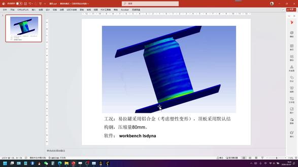 04:35查看AI文稿AI文稿
大家好,今天我们分享一期易拉罐压缩仿真,采用的软件是 wok 奔驰 elsa, 功放是这样的,易拉罐采用非现金铝合金啊,考虑塑形变形顶板采用默认结构钢啊,压缩量是八十毫米。下面我们看一下具体怎么操作。 首先打开 macbook 软件,从左侧拖拽出来 santa 模块,首先进入材料的定义,打开功能数据源 啊,在非现金材料中,我们选择非现金铝合金,点击加号,点击关闭。接下来我们导入我们需要的三维模型, 导入之后我们右键啊用 spaceclaim 进行打开 啊,打开之后我们需要注意的是,呃,其中这个易拉罐,呃,我们采用的是撬单元,它是由两部分组成的,一个是罐身,呃,一个是灌盖,呃,一个是盖子这两部分,那所以说我们需要对这两部分进行一个共享拓扑,我们点击 winch, 点击 share 啊,这里自动识别到了,我们可以点击个对号啊,这样就可以了,我们点击关闭啊,然后我们双击 model 进入,我们开那个界面, 好,打开之后啊,我们可以看到这两个问号,那是因为这个厚度没有赋予我们把厚度设置为零点三毫米啊,同时材料的话赋予为飞线型铝合金。 然后在这个接触里边的话,呃,需要有一点注意啊,我们需要把这个,呃无摩擦改成有摩擦,分别设置为零点一,目的是避免这个压缩过程中易拉罐发生一个滑移啊, 下面我们进行网格划分,呃,对整体网格控制的话,我们可以改成啊六毫米。 然后我们再单独对易拉罐进行一个尺寸控制,首先插入一个方法,我们选择易拉罐, 点击 play 啊,在这里我们可以改成多区域,多区域四边形或三角形,然后再插入一个尺寸, 同样的选择易拉罐,呃,这里的尺寸它是默认是跟全局尺寸是一样的,就刚刚六号,那现在我们把这个改成两毫米,适当缩小一点进行往后划分。 下面我们进进入边界条件的设置, 首先需要给底板,底板这个面加一个固定约束,然后再对顶板加一个位置 位,约束的话可以在外轴啊,但是是加一个,呃,负八十,八十毫米,注意这个时间现在是一秒,咱们现在是在分析设置里边把节约时间改成零点零一秒, 呃,需要注意一点啊,我们需要在这个里面把这个球解器啊用的单位制,呃,需要改成呃,米千克秒, 然后这里我们回到这个 v 一个数,呃,这里看到啊,我们需要把这个进行一个修改啊,改成 f 八十啊,这样就没问题了 啊,然后接下来我们进行求解啊,求解完成之后我们简单看下结果,插入一个总变形,再插入一个等效因子 啊,在显示,这边啊,我们可以把这个改成一比一真实尺寸 啊,可以看一下这个整体的一个效果。 好,这就是本期分享的啊整个内容。
 03:50查看AI文稿AI文稿
我们来看一下 speaking 里面的这个创建新的仕途啊,新的定向仕途怎么样定义相应的这个创建,那比如说我们现在是有这样子的这个鞋面啊,鞋面我想 正式以这个前面咱们就给他创建,那正常来说,我们可以通过这个地方啊,去查看你对应的顶式图啊,或者是我们的底部试图啊,这都是可以进行相应的这个查看。然后如果你要 看某一个指定的仕途呢,我们可以通过这个这个捕捉仕途啊,捕捉仕途,然后点一下他,那么可以看到这个地方就可以捕捉了,但是这个仕途呢?是倾斜的 啊,是倾斜的,那如果你觉得这个试图合适,那对了,我们也可以点这个试图啊,当然你这个可以按住他往这边这一下的拖拽放,把它放到我们的这个右侧 这里面来啊,比如说你觉得这个仕途 ok, 那你可以创建,创建的时候命名,比如说我们的这个啊 a 吧啊 a, 然后确定, 那我要切换成其他试图的时候呢,那对应的我们就可以再点一下这个 a, 那从而他就回回到我们对应的指定的试图,那当然你也可以这个地方你也可以给他创建一个快捷方式啊,快捷方式去去进行的这么一个查看, 这是其中一种,那除了这个种之外呢,我们还可以点这个草会的草会模式,然后选他这个平面,选择平面,然后点这个 点这个啊,这个是我们的这个平面仕途啊,觉得这个仕途不错,那对应的我们可以创建一个新的一个仕途,然后对应的给他 他来一个啊 d 吧,啊 d 那 d 的话,就是当前的这么个试图,那当然你这时候再点的 a 的话,他就转向 a 了啊,当然转到 a 的时候呢,我们这时候再点一下这个试图,那我就可以把这个 a, 这个啊,他进行相应的替换。 这时候我在调整到 d 的时候啊,大家本身他是这个视角,那选择在 a 的时候呢,他又会进相应的这个匹配啊,匹配到我们刚才啊调整的这么一个状态,就说你可以通过这样子 给他做一个替换啊,带你从命名啦、创建啦,这些都可以给他之前的调整应用试图,应用试图就双击嘛,那这是这么一个调整,那后期我如果想在这个试图里面去展现他的这个视角的时候,怎么工程图啊?怎么样去体现他?那我们可以创建一个 图纸,图纸的时候呢?那当然这是默认的啊,默认的,那你可以把他进一箱的删除啊,把他进一箱的这个删除。抵赖啊,把他抵赖,把他删掉, 你想自己去创建的话,对了,我们可以点这个常规,试图点一下他,点他之后呢,我们这个地方啊,这个属性,这里会有相应的这个设置。比如说我们现在是常规啊,我们可以选择地方向 啊,地方下,那么可以看他自动帮你转过来了。那当然你可以选择刚才说的这个 a 的这个试图,但这两个试图基本上是差不多的啊,只是他的一个范围,各方面会不太合适,不太有点差别啊,有点差别,那这个图这个图纸呢? 这样他也是三维的啊,你按住他进箱的这个旋转的时候,他也是三维的,那我们要怎么样回到这样的这个平面视角呢?我们可以点一下这个平面视图,就可以回到我们的平面视图了。 啊,那我就是我们今年讲的这么一个,创建一个新的啊,个自己制定意义的一个定向,定向是图这么一个支点啊,如果大家有问题的话也可以提出来,我们一起啊交流探讨啊,共同进步。


