fisher反馈装置如何调
hi, i'm jim jones with emerson in this video i'm going to show you what you may need to do before you calibrate this fissure thirty five eighty two pneumatic positioner of course we want to always make sure we review and are familiar with all of the safety precautions and procedures found in the instruction manual for the thirty five eighty two positioner okay the positioner has already been properly mounted onto this fissure six five seven size forty eye direct acting actuator we've hooked up the air supply and made sure the regulator is set to the proper pressure in this case twenty psi and we've installed the airline from the positioner to the actuator so let's first identify the components of the positioner that we'll be working with the d shaped beam here is the summing beam and is the component this flapper assembly moves around on notice the summing beam is labeled direct over here and reverse over here the cam which is attached to the rotary shaft feedback arm is behind the summing being down here at the bottom this cam labeled a is the linear cam make sure the arrow on the cam points in the direction of actuator stem travel on this dret acting actuator increasing diaphragm pressure drives the stem down so the arrow must point down the nozzle is located right here the bellows is behind the beam and in the upper right corner there are two pins and one screw that we will adjust in this initial setup procedure one pin is directly above the nozzle and it's called the beam pivot pin the other pin is located just in front of the bellows and is called the bellows pivot pin the screw, we will adjust is on the flapper assembly we want to make sure that the beam is totally perpendicular to the nozzle so the flapper approaches the nozzle squarely to do that we may need to do a beam alignment now if you have a brand new thirty five eighty two positioner you shouldn't need to do this beam alignment procedure, but it doesn't hurt to check it commonly you will need to check beam alignment if the positioner has been rebuilt in any components replaced if the positioner is to be split ranged or the positioner is acting in a non standard way, step one is to loosen the lock nut around the nozzle turn the nozzle in all the way and then back it out four complete turns step two increase the input signal to the middle of the input range in other words on a three to fifteen psi input take the pressure to nine psi step three move the flapper assembly to place it over the cam down here at position zero now check the rotary shaft arm if the index marks on the arm are not aligned with the ones on the case adjust the follower ascent assembly screw until the marks are aligned when they are parallel tighten the lock nut on this assembly this will be the only time we will need to adjust this screw now in step four we move the flapper assembly to the number ten on the direct side of the beam check the feedback arms if they are not parallel adjust the bellows pin using an eighth inch wrench until they are go to the reverse side and check the arms again if they are not parallel adjust the bean pivot pin above the nozzle you may need to repeat this direct ten reverse ten procedure a few times until there is no movement in the arms and they stay parallel regardless of where the flapper assembly is placed if the arms don't move when the flapper assembly is on either side of the summing beam beam alignment is complete just make sure all the lock nuts are tightened the only thing left to do now is to zero and span the positioner, but i'll show you how to do that in another video so the first part of calibrating a fisher thirty five eighty two positioner is making sure the beam is aligned with the nozzle and we can do that in just four easy steps first turn the nozzle all the way in and then out four complete turns next set the input signal to the middle of its range then move the flapper assembly over the cam and adjust the flapper assembly screw to align the feedback arms step four is to move the flapper assembly from direct ten and then to reverse ten to align those arms using both the bellows pin and the beam pivot pin finally when you're all done tighten up the lock nuts and that's it visit fisher com to learn more about the fisher thirty five eighty, two position or to contact your local emerson sales representative thanks for watching。
粉丝313获赞329
相关视频
 03:07查看AI文稿AI文稿
fisher dvc 六二零零定位器如何调试?首先调压接入信号源与 heart, 手操二,用 heart 进行调试。
350给未来的自己 00:54
00:54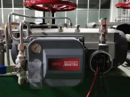 03:07查看AI文稿AI文稿
fisher dvc 六二零零定位器如何调试?首先调压接入信号源与 heart, 手操二,用 heart 进行调试。
 00:58
00:58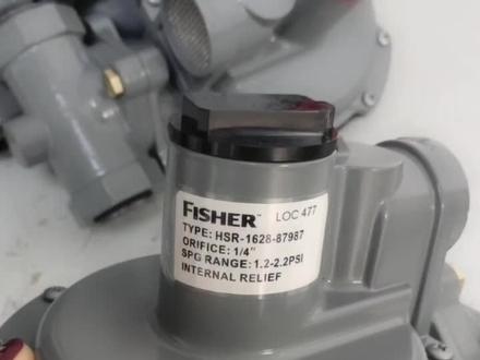 00:22查看AI文稿AI文稿
这是一款费希尔的 hsr 调压阀,教大家怎么调节出口压力。首先我们将盖子打开, 使用一字螺丝刀,就这样顺时针旋转压力增加,反之逆时针压力减小。调好之后我们把盖子盖上。
39买阀门就找陆工 01:12
01:12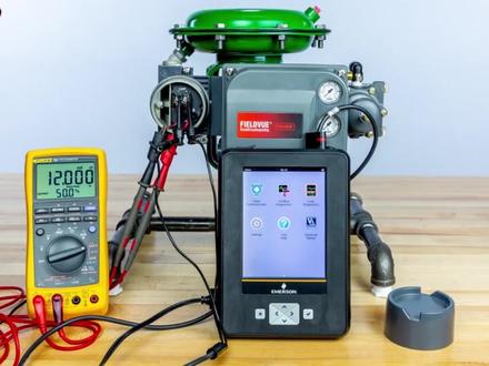 02:25查看AI文稿AI文稿
如何使用 facial web link 状态监控程序?零幺 status 状态监控程序可以让我们监控数字法控制器上的设备参数, 确保设备有足够的电源和通讯期也正确连接时。 status 状态监控应在设备正在使用中运行。在屏幕的右下角,验证设备是否在使用中。 in service 从主菜单中选择图标,打开 status 状态监控。 当状态监控打开时,选择右下角的 start 开始按钮。开始, 设备参数将开始显示在屏幕上, 并随着控制信号的调整和阀门的运动而变化。在这里我们看到设备参数随着控制信号从八毫安、十二毫安、十六毫安和二十毫安的调整发生了变化。 监测这些参数有助于对控制法进行故障排除。可以使用窗口底部的页面选项卡来监控其他信息。 选择了此警报选项,将允许用户监控设备中的任何活动。警报 活动仅报由屏幕左侧的唇色菱形标识。 通过选择右边的箭头,可以 查看有关警报的其他信息。选择 device info 设备信息,可以查看该设备的基本信息,如 heart 标签、仪器等级、物件等。 使用 save data 保存数据选项保存状态监控的信息。 按下 save 保存键,保存设备当前读取的参数记录。此信息保存到通信器中,可以在以后查看。 状态监控完成后,选择当将结束监控并返回主菜单。感谢您的观看,欢迎您点赞关注仪表,堂堂说仪表。


