英飞凌芯片tc1796读写教程
谢谢你,在我二零一一年我最亲密的时候,因为我的公司他们担心承担责罚, 之后呢,在我拿到两百万粉丝的时候,他们进行出要把公司所有的钱都投资,同时告诉我所有的自己的对象,如果不行 之后大家把融资来的钱都占上了,几乎把我逼到绝境。在我发明的一六年,在此想投资的人数两千万的时候,我带着我的好朋友去一群我好朋友进来告诉投资人叫做是我不会。

粉丝3606获赞1.8万
相关视频
 08:32查看AI文稿AI文稿
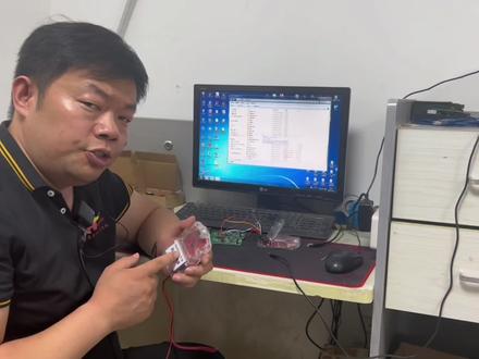
英菲灵设备软件如何安装?芯片数据如何读写?电路图,接线图在哪里?查看这个视频可能稍微有点长,但是我还是希望汽车维修后市场的机士们耐心看完。来,我们先看软件的安装。 第一步,找到对应的资料夹,菲斯卡尔下载菲斯卡二,三个一,下载三个一,英菲零下载,英菲零下载完毕,双击运行安装。第二步,找到程序和接线图两种。第一, p 捷泰科 这种啊,新版本的只需要接四五根线就可以了,老版本的需要接十几根线也是可以的。英菲灵编程器不管是这种的啊,还是这种中文的,那么拿到这个设备之后来 如果是高配的,那么我们打开可以看啊,这上面呢有几个诊断口,那么这个诊断口呢,是针对老协议的啊,杰泰特的就是说他啊,把这个插针穿到这是配合这个啊接口来使用的。 新款的芯片呢,接六根线就可以了,这个上面呢,一般你得接十到十一根线,那么这个呢是 dap 协议,就是这个地方有个穿针啊,你把它导到下边来, 然后就可以用这个接口了。那这个接口和这个接口到底什么时候用呢?根据你拿到的电动图,还有你的芯片支持哪一种毒血,你选择哪一个就行了。 那这两个来讲呢,这个比较快,安全稳定,这个呢比较慢一点啊,我个人的理解是这样的,好了,那么这个电压呢? 调啊,它是自动显示的芯片上电以后的富贵电压,这个地方呢,两个针脚是富贵电压,插到这边是五伏,插到这边是三点三伏,一般情况下咱们的啊,英菲云选择三点三伏, 菲斯卡尔,那么这边呢还有四根线,这四根线是干什么的呢?十二伏的输出啊,他是往外共十二伏的,不是你给他加了十二伏的, ok, 盒子针脚说明不管了,今天呢咱们以奔驰二零六啊大家来看啊,我们接的是六根线,就是 dap 接口的 dp 接口呢,接上之后呢,六根线接完咱 usb 插上,另外呢给咱的机器啊上十二伏电插上就可以了,那么咱们这个有设备有什么好处呢?如果你的线 芯片开始工作了,基本上负一电压三点三伏就出现了,出现三点三伏才有可能使你的机器能读到这个音飞铃芯片里面的数据,如果负一电压都没有上, ok, 你就不用再往下尝试了,几乎不可能读到数据来,我们看如何使用。 ok, 咱们首先呢要有一份自己的啊好的数据,那么我们打开英菲零六点零中文版,咱这个机器是中文,支持中文版。 好,咱们双击 dds 来看一下,如果出现了啊,这个数字就证明咱们的软件 和咱们的芯片已经通讯了,如果你出现的不是这样的数字,只是你的设备的 id 号码,那就证明了咱们的软件和咱们的设备可以正常通讯,但是呢 和芯片它是不通讯的,像这样咱们的芯片就通讯了,然后呢我们把它关掉,运行英菲铃主程序。 进来之后啊,咱们首先呢根据芯片的型号,你去选择在芯片啊替换这个地方新建工程 啊,这个里面呢你就可以选择 n 种的啊,英菲零型号的这种芯片,我们这个呢已经选择好了,咱们就不需要再去选择了,那么进来呢,大家去看啊,这个地方英菲零二七七 t 啊,就是咱们奔驰二零六二二三的都选这个,然后我们连接芯片, ok, 芯片已连接,那么读取的数据是哪几组呢?在这边来看咱们的啊, p plus 零有一组, p plus 一有一组,一方 有一组,还有一组呢, df 一,大家来看啊, note read 就是不可以读啊,也不可以写的数据,那么咱们读写这三个就可以了,按照顺序来也可以,按照一方,然后 flash 来也可以,我的习惯是先按照一方来, 那么在选这个的时候,大家来看啊,这个里面是数据的大小三百八十四,这个数据起始为零叉 af 啊,零零零零零,到这 零叉 af 零五 ff, 我们如何去啊?加载这个,大家记好这两串数字,开头结尾,然后在这点读取,重新给大家新建一个。好,咱们前面呢是 af, 大写零零零零零,后边这个呢,我们是三百八十四,因为上下加他没有三百 八十四,我们只能手动选 a f 零五,然后呢 f f 这 选在这点,你看大小三百八十四点, ok, 这组第一组数据啊,一方的我们就加载进来了,咱们直接点开始就 ok, 数据读出来退出,然后另存尾。看,咱们选择的起始为 af 零零零零, af 零五, ff 和这个的其实结束是对应的,这时候咱们点另存为,哎,你把它存在你自己要保存的位置,比如说我们这个是读出来的一方 啊,一,咱们那边保存,然后呢再去读另外两组数据,以此类推啊,这是 p 零, p 零两 m 啊,从 a 零零零零零开始,到 a 零幺 fm 结束,来我们再来看啊,怎么样去读取?首先呢还是点读取,先把这个删掉, 然后呢,新建,前面是 a 零零零零,后面呢,你可以直接选,也可以在这直接选,也可以手动去打字啊,选择两兆,它自动到 a 零幺 ml, 然后点 ok, 然后点开始。哎,第二组 p plus p 零的开始录制了,然后呢,咱们还有一组 p 一 a 零二到 a 零三, 老老规矩,录取,先把这个删掉,然后新建 也是亮照加在两 mb, ok, a 零三,没问题,开始好,那么如何写入数据呢? 打开找到咱们的啊,全新数据,比如说我们先从 d plus 就一方说起,斜起就是一方斜起,咱们首先呢加载到啊,咱们的 b 就一方数据右侧,咱们也选啊,一方数据在这呢,选择一下,添加选项。哎,大家来看啊, 添加两样对比,没有啊,没有任何错误,咱们在这直接点编程,这就开始写入了,编程是写入 ok, 写入完毕。那么下一步呢,咱们打开 p 零,加载好,右侧选择 p 零, 单击,然后添加选项, p 零,这就添加进来了,好,没有问题,咱们点编程,注意来看啊, p 零开始写入好,写入完毕,退出加载 p 一数据右侧选择 p 一单击啊,然后呢, p 一就选择进来了,选择进来之后,大家来看我们校宴,没有任何问题, 编程好了, p 一两兆数据开始写入, ok, 数据写入完毕。好,这个时候呢,兄弟们千万不要着急收这个线啊,咱们首先呢把电源线,把 usb 线 拔掉,等待将近三十秒之后,咱们呢再次接通 usb, 接通电源。为什么呢?验证一下数据写完了之后,芯片和咱们的设备还能不能通讯了?来咱们重新验证,双击 运行 dsok 通讯正常,然后试试连接芯片,连接芯片 ok, 芯片已连接至此。到现在呢,咱们这个芯片整个的 读写程序才算一个完整的结束。所以说大家在选择芯片啊,数据读写的时候呢,一定要进行最后的一个效验。好了,不管是经验图还是设备的使用方法,今后给大家分享更多的使用技巧。
 00:46查看AI文稿AI文稿
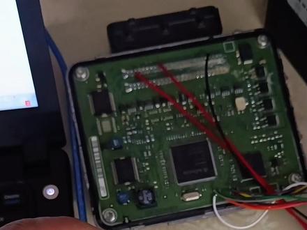
咱们看一下啊,这一个发动机电脑使用的是英菲林的 cpu 啊,使用英菲林的芯片啊的电脑特别多啊,咱们 给老铁们做了一款啊,硬飞零的变声器啊,然后咱们用这个变声器对这个发动机电脑进行读取数据,已经连接成功了啊,点击读取,点击正在读取数据啊,能读取出来啊,没问题,咱们现在写一下数据啊,咱们写一下, 点击选择全部,然后加载编程,现在正在插出战区啊,已经插出成功,现在正在编程啊,正在写数据, 已经变成完成了啊,现在正在消炎,现在是零个效果啊,应消炎完成啊,没问题,咱们就可以对这种发动机电脑进行变成数据啊。
344探索动力汽车电子科技 02:31查看AI文稿AI文稿
大家有没发现最近几年搭载英菲林 tc 芯片的气囊电脑,那奖越来越多了,是我手上拿着的这个就是他是日产车的气囊电脑,他的编号大家看一下啊, 九八八二零六 ct 零哎,他的芯片是 tc 二二二的幺六 f。 那我知道,大家对于老款的一四零叉 c 芯片的气囊电脑,那修起来那叫得心应手,因为啊,有好多年的创作经验。 但是呢,新出来的 tc 芯片的气囊电脑,大家可能有点无从下手啊,不知道怎么搞, 我告诉大家,以后这种芯片的气囊电脑只会越来越多,那怎么修?不用怕,大佬会教到你,给我点个赞就行。这种气囊电脑 接线啊,非常简单,接四种十二伏 gnd, 看高看低,那个软件呢,自带接图,我现在缺个十二伏,我把它补上。 软件说接哪里,我们必须接哪里,一刻不能缺。接完了,我们将设备器连到设备上,点击读故障码, 大家看它的 e c u 编号,九八八二零六 c t 零 i。 读出来了,它的故障码已经标红色了,就是这一个 正面碰撞安全气囊控制单元,系统说明这个气囊电脑储存了一个碰撞故障,我们清故障码就是把这个故障码给它清掉,我们点击一 键修复,大家注意,正在读取 e e p i o m 数据,读取成功,这个呢是原始数据,我们必须要保存,我们点击保存, 现在正在清除故障码,大家耐心等待就可以了。修复完成,正在重新读模块清晰及故障码。大家看,已经没有标注红色的了,我们看前面的对比一下啊, 有一个碰撞故障,我们修复完之后再堵已经没有了,说明这个气囊电脑已经修复成功。日产车的 tc 芯片的气囊电脑已经修复成功,我们把针脚给它拔掉, 那这个气囊电脑我们装车就可以了。大家还想知道什么汽油知识,欢迎评论区留言,我的老王一定会告诉你的。
360CG长广科技 00:39查看AI文稿AI文稿
接口芯片上底什么是接口芯片?该接口电路具有以下功能,一、设置数据的寄存缓冲逻辑,以适应 cpe 和外置设备之间的速度差异。接口通常由一些计存器或弯芯片组成,只要这些芯片足够大,就可以进行批量数据传输。二、 信息格式的转换,如串形和定型转换。三、能够协调信息中 cpu 和外置两者的类型和水平差异,例如水平转换驱动器 数模或模数转换器等。四、协调持续上的差距。五、地址密码和选型功能其实接口芯片还有很重要的第六个功能,下集我们一起来看看吧!
 13:32查看AI文稿AI文稿
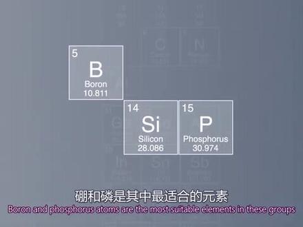
all chips start out with a very simple raw material sand sand is primarily made up of silicon dioxide or silica silicon is the second most abundant element in the earth's crust, but is only ever found as a compound with oxygen complex chemical and physical processes are required to ensure that silicon crystals meet the high production standards that apply to chips to convert silica sand to silicon the sand is combined with carbon and heated to an extremely high temperature to remove the oxygen a number of other steps are required to create the finished product namely an extremely pure mono crystalline silicon ingot called a bull with only one one impurity atom for every ten million silicon atoms silicon bulls are fabricated in a range of different diameters the most common sizes are one hundred fifty two hundred and three hundred millimeters wafers with large diameters offer more space for chips extremely thin wafers are then cut from the silicon bulls using a special sawing technique these wafers are the basic building blocks for subsequent chip production silicon is a semiconductor this means it can conduct electricity and also act as an insulator its atomic structure looks like this every silicon atom has four outer electrons there are no free charge carriers as a result the pure monocrystalline silicon is non conductive at room temperature to allow it to become conductive small quantities of specific atoms are added as impurities to the wafer these impurity atoms must have a number of outer electrons that is either one more or one less than that of silicon silicon is in the fourteenth group of the periodic table of elements this means that elements in the thirteenth or fifteenth group have to be used in this process refer to his doping boron and phosphorus atoms are the most suitable elements in these groups they are very close to silicon on the periodic table and therefore have very similar properties phosphorus has five outer electrons when it is inserted into the silicon crystal lattice the fifth phosphorus electron can move freely this means that the silicon phosphorus crystal is end conductive in contrast boron adams only have three outer electrons when they are introduced into the silicon lattice one silicon electron has nothing to bond to this creates electron holes the holes move through the crystal like positively charged particles making the material peak conductive transistors are built on the p and n conductive layers that exist in a doped wafer transistors are these smallest control units in microchips, their job is to control electric voltages and currents and they are by far the most important components of electronic circuits every transistor on a chip contains p and n conductive layers made of silicon crystals they also have an additional layer of silicon oxide, which acts as an insulator a layer of electrically conductive polysilicon is applied on top of this every transistor has three terminals the middle one is attached to the gate, which is the electrically conductive polysilicon if an electrical charge is applied to only the two outer terminals electricity cannot flow as the transistor is blocked this changes however, if an additional charge is applied to the middle terminal electrons from the player are then pulled toward the middle terminal and accumulate at the area bordering the silicon crystal and the insulating gate oxide a channel then forms underneath the gate between the islands of end conductive material electrons can now flow through this channel。 the electrical circuit is closed in this way, the transistor can be switched back and forth between current enable and disable between zero and one on and off, but how are these layers created on a wafer the process to manufacture chips from a wafer starts with the layout in design phase, highly complex chips are made up of billions of integrated and connected transistors enabling sophisticated circuits such as microcontrollers and crypto chips to be built on a semiconductor's surface measuring just a few square millimeters in size the sheer number of components calls for an in depth design process, this entails defining the chip's functions simulating its technical and physical properties testing its functionality and working out the individual transistor connections special design tools are used to draw up the plans for integrated circuits and develop a three dimensional architecture of sandwich layers this blueprint is transferred to photo masks providing geometric images of the circuits, the photo masks are used as image templates during the subsequent chip fabrication process to ensure that the microscopic structures of a chip are reproduced flawlessly they have to be fabricated in a dust free environment with stable temperature and humidity levels in other words they have to be made in a clean room a clean room is a room in which no more than one particle of dust larger than zero point five micrometers is permitted in around ten leaders of air this is even cleaner than the air in an operating room the ventilation filtration and supply systems in a clean room therefore have to be extremely sophisticated several million cubic meters of air are circulated every hour and hundreds of air volume regulators maintain a constant air flow employees in these production areas have to abide by an extremely strict dress code they are not permitted to smoke before work or where any makeup or jewelry clean room production areas can only be accessed through a special airlock chips are built on a base wafer cut from a silicon bull depending on their size several dozen or several thousand chips can be fabricated on one wafer first of all the surface of the wafer is oxidized in a high temperature furnace operating at approximately one thousand degrees celsius to create a non conductive layer then a photoresist material is uniformly distributed on this non conductive layer using centrifugal force this coating process creates a light sensitive layer the wafer is then exposed to light through the photo mask and special exposure machines known as steppers during this process coaster size areas of the chip ten template known as recticles are used to transfer the complex geometric patterns of the circuit design to the silicon wafer the exposed area of the chip pattern is developed revealing the layer of oxide below the unexposed part remains as is protecting the layer of oxide after this the exposed layer of oxide is etched off in the areas that have been developed using wet or plasma etching with plasma etching special gases bond with the substrate to be removed in the reaction chamber this enables microscopic layers to be removed in the windows that were exposed and developed in the previous step once the photo resist residue has been stripped and the wafer has been cleaned the wafer undergoes further oxidation electrically conductive polysilicon is deposited on this insulation layer then photoresist is applied again and the wafer is exposed to light through the mask, the exposed photo resist is stripped again now the polysilicon and the thin oxide layer are etched off these two layers only remain intact in the center under the photo resist the next step is the doping process where impurity atoms are introduced into the exposed silicon an ion implanter is used to shoot impurity atoms into the silicon this changes the conductivity of the exposed silicon by fractions of a micrometer after the photo resist residue has been stripped another i oxide layer is applied the wafer undergoes another cycle of applying photoresist exposure through the mask and stripping contact holes are etched to provide access to the conductive layers enabling the contacts and interconnections to be integrated in the wafer this is done by depositing metal alloys onto the wafer in sputtering machines once again the photo resist and mask are applied the unexposed strips remain as is after the etching process providing a point of contact to the underlying layers to give the insulation layer above the interconnections the smooth finish it requires a chemical mechanical process is used to polish away excess material with micrometer accuracy these individual staffs may be repeated multiple times in the fabrication process until the integrated circuit is complete depending on the size and type of chip, the wafer will now contain anything from several dozen to thousands of chips individual chips are usually sought out of the wafer, the chips are not lined up flush with each other on the wafer because tiny parts of the wafer splinter off during the sawing process a certain amount of space known as the scribe line is always left between the individual chips test structures are also integrated in the space between the chips and used to take measurements immediately after production, these text structures are destroyed during the sawing process the size of the resulting chips typically varies between one square millimeter and a few square centimeters the final stage of fabrication is assembly here the individual chips are placed in a package and terminals are attached the result is a finished semiconductor device which can be mounted on circuit boards using different types of terminals over a thousand connection context can be realized here are some examples of ready packaged semiconductor components special larger packages are used for power semiconductors intended for applications such as trains, electric cars, solar panels and wind turbines these powers semiconductors are designed to switch electrical currents of up to several hundred amps and voltages that run into the thousands switching at this level generates, high temperatures and this heat has to be dissipated via cooling areas integrated into the packages here you can see some fully packaged power semiconductors cutting edge technologies used for testing at every step in the fabrication process to ensure the highest quality levels in chip, yield researchers and developers use scanning electron microscopes to repeatedly check the chips at different points in the production process if we compare today's microelectronics with human hair we can see just how small these devices are the equipment used to check components and analyze defects is just as precise these high levels of precision and quality are essential at every stage of the workflow from the production of silicon bulls through the cleaning room fabrication to quality control in order to deliver these tiny building blocks that have such a big impact on our lives today and in the future after all demand is rising for innovative semiconductor solutions that make life easier safer and greener for technology that achieves more consumes less and is available to everyone micro electronics is the key to a bad future part of your life part of tomorrow infinian。
785量子时代 15:00查看AI文稿AI文稿
英菲灵是全球半导体解决方案的领导者,致力于让生活更便利、安全和环保。面对人口快速增长、超大城市不断涌现和自然资源日益匮乏等问题, 世界各地的研发专家都在探寻解决这些全球性挑战的创新之道。 数字化转型也将改变我们未来的生活和工作方式。 如何为与日俱增的世界人口供应能源,以满足追求更高生活水平的需求,同时最大限度的减轻环境影响。微电子技术是关键, 微电子也是智能汽车高效能源管理及数据安全存储和传输的基础。 要解决当今社会的挑战,我们离不开半导体。随着现实与数字世界的界限越来越模糊,数字化转型的势头日益迅猛,半导体将扮演更加重要的角色。 数字化正帮助提高工业生产的效率,通过更环保的耕作方式来提高农业产量。它为终端消费者创造新机遇,例如智能家居和网联汽车,促进全球沟通交流, 通过无现金支付让日常生活更便捷。无论你是否意识到,我们生活中的许许多多日常都是由 高度复杂的微电子系统控制的。这些微小的、挤进隐形的微芯片已经成为我们生活中不可或缺的一部分。所有的芯片都源于一种非常简单的原材料沙子。 沙子主要是由二氧化硅和硅酸盐组成。硅是地壳中含量第二丰富的元素,但迄今发现的硅即以含氧化合物的形式存在。为确保硅晶体达到制作芯片所需要的高生产标准, 硅的生产需要非常复杂的物理化学过程。为了将硅砂转化成硅,必须加入碳并加热到极高温度以去除氧,然后还要经历许多其他步骤才能得到成品及纯度极高的 单经规定,也称经定。每一千万个硅原子中只有一个杂质原子规定的直径有大小之分,最常见的有一百五、二百和三百毫米。 通过特殊的切割技术规定被切割成极薄的晶原。晶原直径越大,能给芯片提供的空间就越大, 这些精元是后续芯片生产的基本构建。硅是一种半导体,这意味着他既能导电,又能充当绝缘体。每个硅原子的最外层都有四个嫁电子,但无自由再留子。 因此纯单晶硅在室外下不导电。为了让它能够导电,必须向晶源 中掺入少量的特定原子作为杂质。这些杂质原子的最外层必须拥有一定数量的嫁电子。相比龟,要么多一个,要么少一个。 硅式元素周期表中的第四主族元素,这意味着向精元中掺入的必须是第三或第五主族元素,此过程被称之为掺杂。 彭和林是第三和第五主族中最合适的元素,他们在元素周期表中靠近龟,因此性质非常相似。 林园子最外层有五个架电子,被引入硅晶阁中时,林第五个架 大电子可以自由移动,这意味着归零晶体属于 n 型硅导体。 相反,蓬元子最外层只有三个架电子,被引入到硅金阁中时,硅元子有一个架电子无法形成共架件,这就形成了电子空穴。对 空穴像正电鹤离子一样在晶体中移动,从而形成 p 型硅导体。晶体管构建在掺杂晶源中的 p 型和 n 型导电层上。 晶体管是微芯片中最小的控制单元,他们负责控制电压和电流,是电子电路迄今为止最重要的原件。 芯片上的每个晶体管都含有由硅晶体制成的 p 型和 n 型导电层,他们还有一层额外的二氧化硅,起到绝缘体的作用,在这上面加有一层导电多晶硅。 每个晶体管有三个电极,中间电极与属于导电多晶硅的山极相连。 如果只给另两个外层电极上电,由于晶体管被关断,电流无法流动,但如果再给中间电极上电,就能改变这种局面。 来自 p 型导电层的电子被拉向中间电极,聚集在硅晶体和 原山极氧化层的交界区域中,然后在 n 型导电电极之间的山极下面就形成了一个勾道,电子就可以通过这个勾道流动, 从而形成闭合电路。如此,晶体管即可在电流导通和关、断、零和一及开和关之间来回切换。但这些是如何构建到晶源上的呢? 从精元到芯片的制造过程始于版图和设计阶段。高度复杂的芯片由数十亿个互联集成的晶体管组成, 使得微控制器和加密芯片等复杂电路能被构建在只有几平方毫米大小的半导体表面上。 原件数量之多使得深入的设计过程必不可少。这需要明确芯片的功能,模拟他的技术和物理特性,进行功能测试,并完成单个晶体管的连接。 利用特殊设计工具绘制出竭诚电路的平面图,并构建出三维的三层结构图。该设计图被转移到眼膜上。眼膜在之后的芯片制造工具中用作图形模板,以提供电路的几何图形。 为保证能够完美无缺的再现芯片的微观结构,必须在温度和湿度均稳定的无尘环境中制造芯片,也就是说, 必须在洁净室中制造芯片。洁净室是指在约一立方米空气中不允许有一粒以上超过零点五微米灰尘的房间,这种洁净度比手术室里的空气还要高。 洁净式的通风、过滤和供电系统因此必须极其复杂。洁净式每小时流通的风量达到数百万立方米, 有数百个风量调节装置维持空气流量恒定。在这种生产区域工作的员工必须遵守极其严格的着装规定,他们在上班前不允许吸烟, 也不允许化妆或佩戴首饰,只能通过专门的气闸式进入洁净式生产区。 芯片构建在由规定切割而来的机片上,取决于芯片尺寸。在一颗晶原上可以制造几十或几千颗芯片。 首先,晶原表面在大约一千摄氏度的高温炉中氧化形成非导电层,然后利用离心力将光刻胶均匀的涂布到该非导电层上,由此形成一个光敏层。 然后在称之为步近视的专用光刻机中透过眼膜给精元曝光。 在此过程中,通过芯片模板上杯托大小的区域又称模板。电路设计的复杂几何图形被转移到龟片上。 芯片图案的曝光区域被显影,露出下面的氧化物层,未曝光的部分保持原样用于保护氧化物层。 此后在一使用施法或等离子时刻鲜硬的区域中时刻掉暴露的氧化物层。在等离子时刻中,特殊气体要与衬底反应,并将在反应适中被除去, 这使得可在上一步曝光和显硬的窗口中除去微观层精元在除去光刻胶残留 清洗之后进行进一步的氧化。一是导电多金龟被沉积到该绝缘层上,然后再次徒步光刻胶,并透过眼膜给星缘曝光。 再次剥离曝光的光刻胶之后时刻掉多金龟和保养化物层,只在光刻胶下面的中心位置将这两层保持完整。 接下来是掺杂工序,需在暴露的硅中引入杂质原子。利用离子注入机将杂质原子轰击到硅片中。这颗使暴露的硅片表面几分之一微米 导电性发生改变。除去光刻胶残留后,再生长一层氧化物层精源,再进行一次徒步光刻胶,透过眼膜曝光和玻璃曝光。光刻胶的过程 时刻接触孔供导电层访问,使得接触孔与互联能被集成到精元中。 这一步需要用建设机将金属合金沉积到晶原表面。 再次徒步光刻胶和眼膜曝光为曝光的部分保持原样。时刻工艺用于提供与底层的接触点。 为了使互联结构上面的绝缘层具有所需的光滑表面,利用微米级精度的化学机械研磨工艺 磨去多余的绝缘层。在集成电路完成之前,这些单独的工具可在芯片制成中重复多次,取决于芯片的大小和类型。 京元如今可以容纳几十乃至几千颗芯片。 单颗芯片通常是从精元上切割下来的,由于在切割过程中会有极小的精元碎片脱落,因此精元上面的芯片彼此并非完全保持齐平。 单颗芯片彼此之间永远留有一定的空间,称之为画片槽。测试结构也被集 承在芯片之间的这一空间中,用于在完成生产后立即开展检测。这些测试结构在切割过程中被毁掉。 切割下来的芯片尺寸通常在一平方毫米到几平方厘米之间。 芯片制造的最后一步是封装,就是将单颗芯片置于封装中并装上端子,由此获得可以利用不同类型的端子装到电路板上的成品。半导体器件连接触点可以达到近千个。 视频中展示的就是一些带封装的半导体元件。对于面向列车、电动汽车、太阳能电池板和风力发电机等应用 的功率半导体,需要使用较大型的特殊封装。这些功率半导体将用于控制高达几百安培的电流和数千伏的电压。 这种水平下的开关会产生很高的温度,而这一热量必须通过集成在封装中的散热区被耗散掉。接下来我们来看一些完全封装好的功率半导体。 芯片制成中的每一步都使用了先进的测试技术,以确保质量水平和芯片量率达到最高。研发人员利用扫描电磁显微镜 在生产过程中的不同节点反复的检查芯片。 如果将当今的微电子与人的头发丝相比,我们就能知道这些器件有多小。用于检查器件和分析缺陷的设备精度同样很高, 为了制造出这些对我们现在和未来的生活有很大影响的极小器件,高精度和高质量,在芯片制造的每一个阶段都必不可少。 从规定生产到洁净式生产,再到质量控制,我们可以看到,随着经济的发展和生活水平的提高,社会对于更便利、安全、环保的创新半导体解决方案的需求在不断增加。
165半导体社区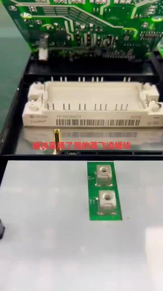 00:14
00:14 04:09
04:09 01:12查看AI文稿AI文稿
好兄弟们给大家做个声明啊,小黄河,菲斯卡尔,全功能带路虎,接头带保时捷都是全功能的,幺幺五零这个价格顶住了各方的压力,坚持到今天,没办法了,今天幺幺五零正式 下线,从此以后不会再出现,那么活动就是活动,不管你是之前看到了在犹豫的,不好意思,没有任何人有策略。 那么今天我再给大家推荐一个英菲灵的啊编程器,那么这个编程器呢?给大家配了三套软件,一个 tle 的,专门写咱们吉利啊, ptc 加热器的, 必须用它。那么还配备了新版的啊,英菲零六点零英文的和六点零中文版本的软件全都有了, ok, 三套软件两 t 的价格,今天明天,后天,三天的时间,八八八我们开启一个活动, 三天之后恢复原,谁也没有特例,谁也没有特权。我再次说明,其他的兄弟们也不用再给我施加压力,活动我只搞三天,主板的做工点个赞,部件的版本注意 是三点一的,不懂行的不要纠结,也不要墨迹,等人家抢完单用过之后,你再去懂行的右下角抓紧下单。
 01:13查看AI文稿AI文稿
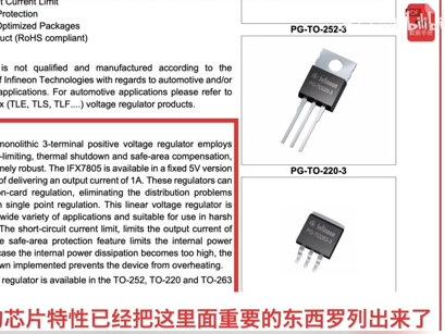
接下来给大家简单讲一下怎么看数据手册,去哪看数据手册?以经典的七八零五电源芯片为例,在数据手册的第一页,首先告诉了我们这个电源芯片的特性,它可以输出一般的电流, 可承受的最大电压为三十五伏,温度范围是零下四十到零上一百二十五度, 同时兼具了过热保护和短路保护,意思是他能在短路或者温度过高时自动断开这个芯片。厂家非常有良心,他在这里告诉我们此芯片不能应用在汽车领域,以往我们错误的将它应用在汽车领域。 接下来是关于他的一些描述,一般我们不用看,因为上面的芯片特性已经把这里面重要的东西罗列出 出来了。最右边的是这个芯片可以选择的三个封装,这一页是七八零五的内部原理框图, 这里告诉我们关于七八零五的各个领奖的定义,这是关于七八零五的一些极限参数,在我们使用过程中不能超过这个值,否则芯片可能彻底损坏。好了,先说。


猜你喜欢
- 238雨晴